Nissan Maxima Service and Repair Manual: Steering gear and linkage
Exploded View
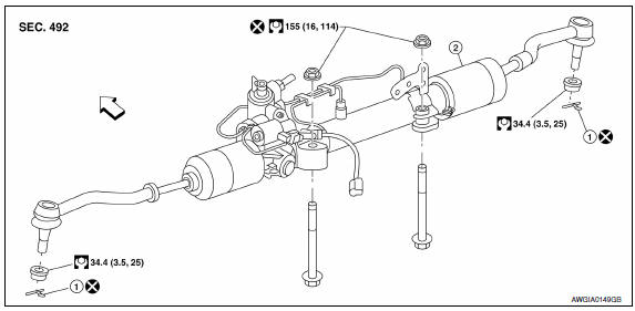
- Cotter pin
- Steering gear assembly
 Front
Front
Removal and Installation
NOTE: When removing components such as hoses, tubes/lines, etc., cap or plug openings to prevent fluid from spilling.
REMOVAL
- Remove front wheel and tire using power tool. Refer to WT-60, "Adjustment".
- Drain power steering fluid. Refer to ST-12, "Draining".
- Disconnect front stabilizer connecting rods from front stabilizer and reposition front stabilizer. Refer to FSU-11, "Removal and Installation".
- Remove steering outer socket cotter pins (1), and then loosen the nuts.
- Remove steering outer sockets (2) from steering knuckles (3) so as not to damage ball joint boots (4) using Tool.
CAUTION: Temporarily tighten the nut to prevent damage to threads and to prevent the Tool from suddenly coming off.
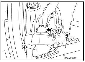
Tool number : HT72520000 (J-25730-A)
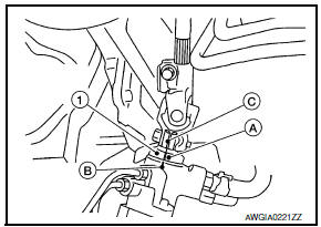
- Remove side bolt (A) of lower shaft assembly (1) and disconnect lower
shaft assembly.
- Steering gear assembly (2) - Remove front exhaust tube. Refer to EX-5, "Removal and Installation".
- Disconnect the harness connector from the SSPS valve. Refer to ST-33, "Exploded View".
- Disconnect high and low pressure piping from steering gear assembly. Refer to ST-29, "Exploded View"
- Remove steering hydraulic piping bracket from front suspension member.
- Remove bolts and nuts of steering gear assembly, and then remove steering gear assembly from vehicle.
INSPECTION AFTER REMOVAL
Check for fluid leaks or damage to steering gear assembly. If any exist, replace steering gear assembly.
INSTALLATION
Installation is in the reverse order of removal.
CAUTION:
- Do not reuse cotter pins.
- Do not reuse steering gear assembly nuts.
- When installing lower shaft assembly to steering gear assembly, follow the procedure listed below.
- Set rack of steering gear in the neutral position.
NOTE: To get the neutral position of rack, turn gear sub-assembly and measure the distance of inner socket, and then measure the intermediate position of the distance.
- Align rear cover cap projection (A) with the marking position (B) of gear housing assembly.
- Install slit part of lower shaft assembly (C) aligning with the projection (A) of rear cover cap (1). Make sure that the slit part of lower shaft assembly (C) is aligned with both the projection (A) of rear cover cap (1) and the marking position (B) of gear housing assembly.
- Connect the high and low pressure piping to the steering gear.
Tighten to specification. Refer to ST-30, "Removal and Installation".
- After installation, bleed air from the steering hydraulic system.
Refer to ST-12, "Inspection".
- Check wheel alignment.
INSPECTION AFTER INSTALLATION
Make sure that steering wheel operates smoothly by turning several times from full left stop to full right stop.
 Steering column
Without Electric Motor
-4. Steering column assembly nut tightening order
Steering wheel
Combination switch and spiral cable
Steering column assembly
Hole cover seal
Herbie c ...
 Power steering oil pump
Exploded View
Rear bracket
Power steering oil pump assembly
Front bracket
Removal and Installation
NOTE: When removing components such as
hoses, tubes/lines, etc., cap or plug open ...
Other materials:
The oil pressure warning lamp does not turn off
Description
The oil pressure warning lamp remains illuminated while
the engine is running (normal oil pressure).
Diagnosis Procedure
Regarding Wiring Diagram information, refer to MWI-87,
"Wiring Diagram".
1.CHECK OIL PRESSURE WARNING LAMP
Perform IPDM E/R auto active test. Refer to PCS-11, ...
Oil pan
Exploded View
Transaxle assembly
Oil pan bolt
Drain plug
O-ring
Oil pan
Oil pan gasket
Magnet
Apply CVT Fluid NS-2
Removal and Installation
REMOVAL
Drain CVT fluid from CVT. ...
Preparation
Special Service Tool
The actual shapes of the tools may differ from those illustrated her
Commercial Service Tool
...
Nissan Maxima Owners Manual
- Illustrated table of contents
- Safety-Seats, seat belts and supplemental restraint system
- Instruments and controls
- Pre-driving checks and adjustments
- Monitor, climate, audio, phone and voice recognition systems
- Starting and driving
- In case of emergency
- Appearance and care
- Do-it-yourself
- Maintenance and schedules
- Technical and consumer information
Nissan Maxima Service and Repair Manual

0.0073