Nissan Maxima Service and Repair Manual: Power steering oil pump
Exploded View
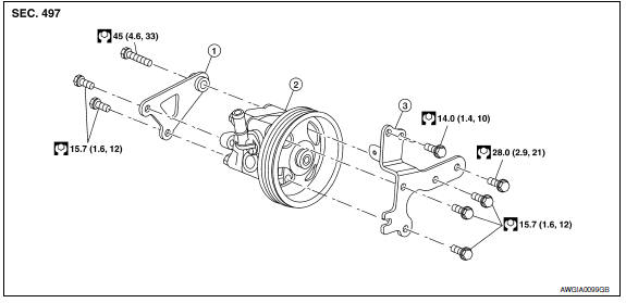
- Rear bracket
- Power steering oil pump assembly
- Front bracket
Removal and Installation
NOTE: When removing components such as hoses, tubes/lines, etc., cap or plug openings to prevent fluid from spilling.
REMOVAL
- Remove front wheel and tire (RH) using power tool. Refer to WT-60, "Adjustment".
- Remove front fender protector side cover. Refer to EXT-23, "Exploded View".
- Remove hood ledge cover (RH).
- Drain power steering fluid. Refer to ST-12, "Draining".
- Disconnect the power steering pressure sensor harness connector at the high pressure pipe. Refer to ST- 29, "Exploded View".
- Disconnect high pressure piping and suction hose from power steering oil pump. Refer to ST-29, "Exploded View".
- Loosen drive belt. Refer to EM-14, "Removal and Installation".
- Remove drive belt from power steering oil pump pulley.
- Remove power steering oil pump bolts, and then remove power steering oil pump.
INSTALLATION
Installation is in the reverse order of removal.
- When installing power steering oil pump, install all bolts by hand initially, then tighten bolts to specification.
- Perform the following procedures after installing.
- Check belt tension. Refer to EM-14, "Checking Drive Belts".
- Bleed air from power steering system.
 Steering gear and linkage
Exploded View
Cotter pin
Steering gear assembly Front
Removal and Installation
NOTE: When removing components such as
hoses, tubes/lines, etc., cap or plug openings to prevent fluid ...
 Hydraulic line
Exploded View
High pressure hose
Suction hose
Reservoir tank bracket
Reservoir tank
Oil pump assembly
Steering gear assembly
Low pressure piping
Eye bolt
High pressure pipin ...
Other materials:
P014C, P014D, P014E, P014F, P015A, P015B, P015C, P015D A/F sensor
1
Description
The air fuel ratio (A/F) sensor 1 is a planar one-cell limit current sensor.
The sensor element of the A/F sensor 1 is composed an electrode
layer, which transports ions. It has a heater in the element.
The sensor is capable of precise measurement = 1, but also in the
lean ...
Front door speaker
Removal and Installation
REMOVAL
Remove the front door finisher. Refer to INT-18, "Removal and
Installation".
Remove the front door speaker screws (A).
Disconnect the harness connector from the front door speaker
(1) and remove.
Remove the front door speaker spacer screws (B) and ...
Exhaust Manifold And Three Way Catalyst
Exploded View
Gasket
Exhaust manifold (RH)
Exhaust manifold heat shield (RH)
Air fuel ratio sensor 1 (bank 1)
Ring gasket
Three way catalyst (bank 1)
Three way catalyst support (bank 1)
Heated oxygen sensor 2 (bank 1)
Three way catalyst (bank 2)
Three way catalyst suppor ...
Nissan Maxima Owners Manual
- Illustrated table of contents
- Safety-Seats, seat belts and supplemental restraint system
- Instruments and controls
- Pre-driving checks and adjustments
- Monitor, climate, audio, phone and voice recognition systems
- Starting and driving
- In case of emergency
- Appearance and care
- Do-it-yourself
- Maintenance and schedules
- Technical and consumer information
Nissan Maxima Service and Repair Manual

0.0067