Nissan Maxima Service and Repair Manual: Front door switch (driver side)
Description
Detects front door LH open/close condition.
Component Function Check
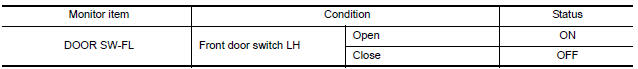
1. CHECK FUNCTION
- Select "DOOR SW-FL" in "DATA MONITOR" mode with CONSULT.
- Check the front door switch signal under the following conditions
Diagnosis Procedure
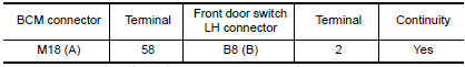
1. CHECK FRONT DOOR SWITCH LH CIRCUIT
- Turn ignition switch OFF.
- Disconnect BCM.
- Check continuity between BCM connector and front door switch LH connector.
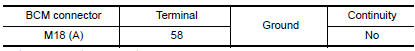
- Check continuity between BCM connector and ground.
2. CHECK FRONT DOOR SWITCH LH
3. CHECK INTERMITTENT INCIDENT
Component Inspection
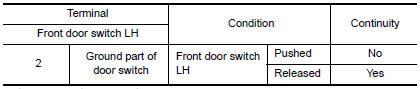
1. CHECK FRONT DOOR SWITCH LH
- Turn ignition switch OFF.
- Disconnect front door switch LH.
- Check continuity between front door switch LH terminals.
 Tilt &telescopic switch ground circuit
Diagnosis Procedure
1. CHECK ADP STEERING SWITCH (TILT & TELESCOPIC SWITCH) GROUND CIRCUIT
Turn ignition switch OFF.
Disconnect ADP steering switch (tilt & telescopic switch).
Che ...
 Sliding sensor
Description
The sliding sensor is installed to the seat frame.
The pulse signal is input to the driver seat control unit when sliding
is performed.
The driver seat control unit counts the p ...
Other materials:
B210E starter relay
DTC Logic
DTC DETECTION LOGIC
NOTE:
If DTC B210E is displayed with DTC
U1000, first perform the trouble diagnosis for DTC U1000. Refer to
SEC-29, "DTC Logic".
If DTC B210E is displayed with DTC
U1010, first perform the trouble diagnosis for DTC U1010. Refer to
SEC-30, "D ...
P2119 electric throttle control actuator
Description
Electric throttle control actuator consists of throttle control motor,
throttle position sensor, etc.
The throttle control motor is operated by the ECM and it opens and closes the
throttle valve.
The throttle position sensor detects the throttle valve position, and the
openi ...
B1017 - B1022 occupant classification system
Description
DTC B1017 - B1022 OCCUPANT CLASSIFICATION SYSTEM (OCS)
The occupant classification system control unit is wired to the air bag
diagnosis sensor unit. The air bag diagnosissensor unit will monitor the
occupant classification system for control unit and sensor mat failures and
inter ...
Nissan Maxima Owners Manual
- Illustrated table of contents
- Safety-Seats, seat belts and supplemental restraint system
- Instruments and controls
- Pre-driving checks and adjustments
- Monitor, climate, audio, phone and voice recognition systems
- Starting and driving
- In case of emergency
- Appearance and care
- Do-it-yourself
- Maintenance and schedules
- Technical and consumer information
Nissan Maxima Service and Repair Manual

0.0062