Nissan Maxima Service and Repair Manual: Sliding sensor
Description
- The sliding sensor is installed to the seat frame.
- The pulse signal is input to the driver seat control unit when sliding is performed.
- The driver seat control unit counts the pulse and calculates the sliding amount of the seat.
Component Function Check
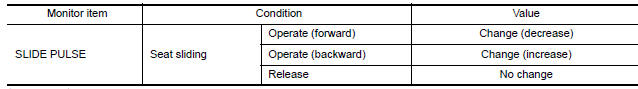
1. CHECK FUNCTION
- Select "SLIDE PULSE" in "DATA MONITOR" mode with CONSULT.
- Check sliding sensor switch signal under the following conditions.
Diagnosis Procedure
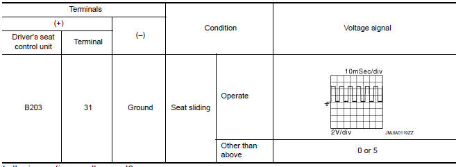
1. CHECK SLIDING SENSOR SIGNAL
- Turn ignition switch ON.
- Read voltage signal between driver seat control unit harness connector and ground with oscilloscope.
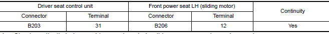
2. CHECK SLIDING SENSOR CIRCUIT
- Turn ignition switch OFF.
- Disconnect driver seat control unit and front power seat LH (sliding motor).
- Check continuity between driver seat control unit harness connector and front power seat LH (sliding motor) harness connector
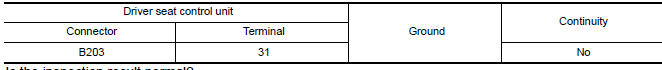
- Check continuity between driver seat control unit harness connector and ground.
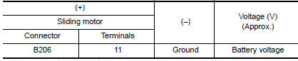
3. CHECK SLIDING SENSOR POWER SUPPLY
- Connect driver seat control unit.
- Turn ignition switch ON.
- Check voltage between front power seat LH (sliding motor) harness connector and ground
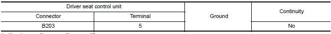
4. CHECK SLIDING SENSOR POWER SUPPLY CIRCUIT
- Turn ignition switch OFF.
- Disconnect driver seat control unit.
- Check continuity between driver seat control unit harness connector and front power seat LH (sliding motor) harness connector.

- Check continuity between driver seat control unit harness connector and ground
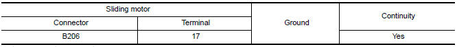
5. CHECK SLIDING SENSOR GROUND
- Turn ignition switch OFF.
- Check continuity between front power seat LH (sliding motor) harness connector and ground.
 Front door switch (driver side)
Description
Detects front door LH open/close condition.
Component Function Check
1. CHECK FUNCTION
Select "DOOR SW-FL" in "DATA MONITOR" mode with CONSULT.
Check the front door switch signal ...
 Reclining sensor
Description
The reclining motor is installed to the seatback assembly.
The pulse signal is input to the driver seat control unit when the
reclining is operated.
The driver seat control unit ...
Other materials:
Step lamp circuit
Description
Controls the step lamp (ground side) to turn the step lamp ON and OFF.
Component Function Check
CAUTION: Before performing the diagnosis,
check that the following is normal.
Battery saver output/power supply
Step lamp bulbs
1.CHECK STEP LAMP OPERATION
CONSULT
Turn igni ...
Both side headlamps (LO) are not turned on
Description
The headlamps (both sides) do not turn ON in any lighting switch setting.
Diagnosis Procedure
1.CHECK COMBINATION SWITCH (LIGHTING AND TURN SIGNAL SWITCH)
Check the combination switch (lighting and turn signal switch).
2.CHECK HEADLAMP (LO) REQUEST SIGNAL INPUT
CONSULT DATA MONITOR ...
Combination meter
Removal and Installation
REMOVAL
Disconnect the negative battery terminal. Refer
to PG-67, "Removal and Installation (Battery)".
Remove the cluster lid A. Refer to IP-16,
"Removal and Installation".
Remove the combination meter screws (A) using
powe ...
Nissan Maxima Owners Manual
- Illustrated table of contents
- Safety-Seats, seat belts and supplemental restraint system
- Instruments and controls
- Pre-driving checks and adjustments
- Monitor, climate, audio, phone and voice recognition systems
- Starting and driving
- In case of emergency
- Appearance and care
- Do-it-yourself
- Maintenance and schedules
- Technical and consumer information
Nissan Maxima Service and Repair Manual

0.0057