Nissan Maxima Service and Repair Manual: Reclining sensor
Description
- The reclining motor is installed to the seatback assembly.
- The pulse signal is input to the driver seat control unit when the reclining is operated.
- The driver seat control unit counts the pulse and calculates the reclining amount of the seat.
Component Function Check
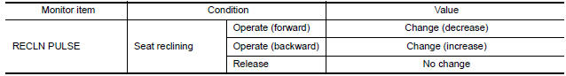
1. CHECK FUNCTION
- Select "RECLN PULSE" in "DATA MONITOR" mode with CONSULT.
- Check reclining sensor signal under the following conditions
Diagnosis Procedure
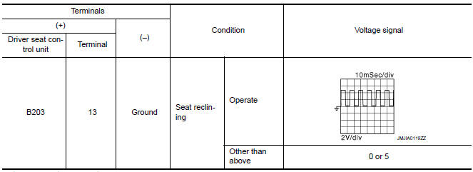
1. CHECK RECLINING SENSOR SIGNAL
- Turn ignition switch ON.
- Read voltage signal between driver seat control unit harness connector and ground with oscilloscope.
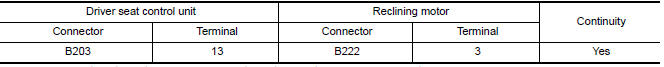
2. CHECK RECLINING SENSOR CIRCUIT
- Turn ignition switch OFF.
- Disconnect driver seat control unit and reclining motor.
- Check continuity between driver seat control unit harness connector and reclining motor harness connector.
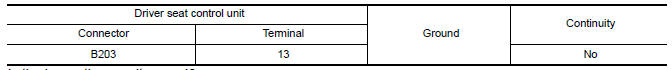
- Check continuity between driver seat control unit harness connector and ground
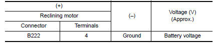
3. CHECK RECLINING SENSOR POWER SUPPLY
- Connect driver seat control unit.
- Turn ignition switch ON.
- Check voltage between reclining motor harness connector and ground.
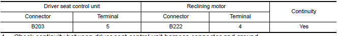
4. CHECK RECLINING SENSOR POWER SUPPLY CIRCUIT
- Turn ignition switch OFF.
- Disconnect driver seat control unit.
- Check continuity between driver seat control unit harness connector and reclining motor harness connector.
- Check continuity between driver seat control unit harness connector and ground.

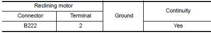
5. CHECK RECLINING SENSOR GROUND
- Turn ignition switch OFF.
- Check continuity between reclining motor harness connector and ground
 Sliding sensor
Description
The sliding sensor is installed to the seat frame.
The pulse signal is input to the driver seat control unit when sliding
is performed.
The driver seat control unit counts the p ...
 Lifting sensor (front)
Description
The lifting sensor (front) is installed to the seat frame.
The pulse signal is input to the driver seat control unit when the
lifting (front) is operated.
The driver seat contro ...
Other materials:
Door lock function
DOOR LOCK AND UNLOCK SWITCH
DOOR LOCK AND UNLOCK SWITCH : System Diagram
DOOR LOCK AND UNLOCK SWITCH : System Description
DOOR LOCK FUNCTION
Functions Available by Operating the Door Lock and Unlock Switches on
Driver Door and Passenger Door
Interlocked with the locking operation o ...
Rear window defogger system
System Diagram
System Description
Operation Description
When rear window defogger switch is turned ON while ignition
switch is ON, the A/C auto amp. (rear window
defogger switch) transmits rear window defogger switch signal to BCM.
BCM turns rear window defogger relay ON when rear ...
The ambient temperature display is incorrect
Description
The displayed ambient air temperature is higher
than the actual temperature.
The displayed ambient air temperature is lower
than the actual temperature.
Diagnosis Procedure
1.COMBINATION METER INPUT SIGNAL
Select "METER/M&A" on CON ...
Nissan Maxima Owners Manual
- Illustrated table of contents
- Safety-Seats, seat belts and supplemental restraint system
- Instruments and controls
- Pre-driving checks and adjustments
- Monitor, climate, audio, phone and voice recognition systems
- Starting and driving
- In case of emergency
- Appearance and care
- Do-it-yourself
- Maintenance and schedules
- Technical and consumer information
Nissan Maxima Service and Repair Manual

0.0065