Nissan Maxima Service and Repair Manual: Intelligent key interlock function
INTELLIGENT KEY INTERLOCK FUNCTION : System
INTELLIGENT KEY INTERLOCK FUNCTION : System Description
OUTLINE
When unlocking doors by using Intelligent Key or door request switch (driver side), seat slide and steering tilt move directly to the exit assist function.
Other loads move to the exit assist function after performing memory function.
Then performs the entry assist function.
OPERATION PROCEDURE
- Unlock doors by using Intelligent Key or door request switch (driver side) .
- The system performs exit assist operation and memory operation.
NOTE: Further information for Intelligent Key interlock function. Refer to Owner's Manual.
OPERATION CONDITION
Satisfy all of the following items. The Intelligent Key interlock function is not performed if these items are not satisfied.
| Item | Request sta |
| Ignition position | OFF |
|
Switch inputs
|
OFF (Not operated) |
| CVT selector lever | P position |
DETAIL FLOW
| Order | Input | Output | Control unit condition |
| 1 |
|
- | Driver seat control unit receives the door unlock signal and the key ID signal from BCM when unlocking the door with Intelligent Key or driver side door request switch. |
| 2 | - | - | Driver seat control unit performs the seat slide and steering tilt move directly to the exit assist function. Other loads move to the exit assist function after performing memory function. |
| 3 | - | - | Driver seat control unit performs the entry assist function |
INTELLIGENT KEY INTERLOCK FUNCTION : Component Parts Location
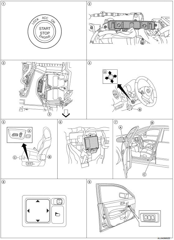
- Push-button ignition switch M38
- BCM M16, M17, M18, M19 (view with instrument panel removed)
- TCM F15
- A. ADP steering switch M39
B. Tilt motor M71, telescopic motor M73 - A. Power seat switch LH B213
B. Reclining motor B222
C. Driver seat control unit B203, B211 - Automatic drive positioner control unit M63, M67 (view with instrument panel removed
- A. Door mirror LH D4
B. Door mirror RH D107
C. Front door switch LH B8 - Door mirror remote control switch M108
- Seat memory switch D13
 : Front
INTELLIGENT KEY INTERLOCK FUNCTION : Component Description
CONTROL UNITS
| Item | Function |
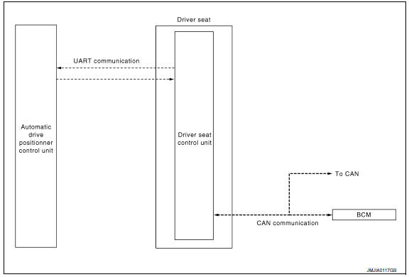
| Driver seat control unit | It performs memory function and entry/exit assist function after receiving the door unlock signal from BCM |
| Automatic drive positioner control unit | Operates the steering column and door mirrors with the instructions from the driver seat control unit |
| BCM |
Recognizes the following status and transmits it to the driver seat control unit via CAN communication.
|
 Entry assist function
ENTRY ASSIST FUNCTION : System Diagram
ENTRY ASSIST FUNCTION : System Description
OUTLINE
The seat is in the exiting position when either following condition is
satisfied, the seat returns fr ...
 Diagnosis system (driver seat C/U)
Diagnosis Description
The auto drive positioner system can be checked and diagnosed for component
operation with CONSULT.
DIAGNOSTIC MODE
Diagnostic mode [AUTO DRIVE POS.]
Description
...
Other materials:
Brake warning lamp
Description
NOTE:
1: Brake warning lamp will turn on in case of parking brake operation
(when switch is ON) or of brake fluid level switch operation
(when brake fluid is insufficient).
2: After starting engine, brake warning lamp is turned off.
Component Function Check
1.B ...
Interior trunk lid release
WARNING
Closely supervise children when they are
around cars to prevent them from playing
and becoming locked in the trunk where
they could be seriously injured. Keep the
car locked, with the rear seatback and
trunk lid securely latched when not in use,
and prevent children's access to ca ...
Power seat for driver side
Wiring Diagram - Without Automatic Drive Positioner
...
Nissan Maxima Owners Manual
- Illustrated table of contents
- Safety-Seats, seat belts and supplemental restraint system
- Instruments and controls
- Pre-driving checks and adjustments
- Monitor, climate, audio, phone and voice recognition systems
- Starting and driving
- In case of emergency
- Appearance and care
- Do-it-yourself
- Maintenance and schedules
- Technical and consumer information
Nissan Maxima Service and Repair Manual

0.0075