Nissan Maxima Service and Repair Manual: B210E starter relay
DTC Logic
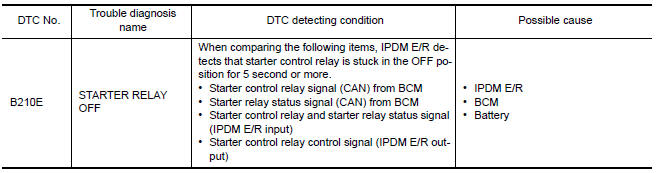
DTC DETECTION LOGIC
NOTE:
-
If DTC B210E is displayed with DTC U1000, first perform the trouble diagnosis for DTC U1000. Refer to SEC-29, "DTC Logic".
-
If DTC B210E is displayed with DTC U1010, first perform the trouble diagnosis for DTC U1010. Refer to SEC-30, "DTC Logic".
-
When IPDM E/R power supply voltage is low (Approx. 7 - 8 V for about 1 second), the DTC B210F may be detected.
DTC CONFIRMATION PROCEDURE
1.PERFORM DTC CONFIRMATION PROCEDURE
-
Turn ignition switch ON under the following conditions and wait for at least 1 second.
-
CVT selector lever is in the P (Park) or N (Neutral) position
-
Do not depress the brake pedal
-
-
Check Self-diagnostic result with CONSULT.
Diagnosis Procedure
Regarding Wiring Diagram information, refer to SEC-147, "Wiring Diagram".
1. PERFORM SELF DIAGNOSTIC RESULT
Perform Self Diagnostic Result of IPDM E/R using CONSULT.
2.CHECK STARTER CONTROL RELAY CONTROL CIRCUITS VOLTAGE
Check voltage between IPDM E/R connectors and ground.

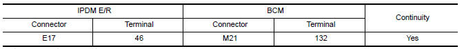
3.CHECK STARTER CONTROL RELAY CONTROL CIRCUIT CONTINUITY
-
Disconnect IPDM E/R connector E17 and BCM connector M21.
-
Check continuity between IPDM E/R connector E17 and BCM connector M21.
 B210D starter relay
DTC Logic
DTC DETECTION LOGIC
NOTE:
If DTC B210D is displayed with DTC
U1000, first perform the trouble diagnosis for DTC U1000. Refer to
SEC-29, "DTC Logic".
If DTC B210D is di ...
 B210F transmission range switch
Description
IPDM E/R confirms the shift position with the following
signals.
Transmission range switch
Shift position signal from BCM (CAN)
DTC Logic
DTC DETECTION ...
Other materials:
B210D starter relay
DTC Logic
DTC DETECTION LOGIC
NOTE:
If DTC B210D is displayed with DTC
U1000, first perform the trouble diagnosis for DTC U1000. Refer to
SEC-29, "DTC Logic".
If DTC B210D is displayed with DTC
U1010, first perform the trouble diagnosis for DTC U1010. Refer to
SEC-30, "D ...
P0500 VSS
Description
ECM receives vehicle speed signals from two different paths via CAN
communication line: One is from the
ABS actuator and electric unit (control unit) via the combination unit and the
other is from TCM.
DTC Logic
DTC DETECTION LOGIC
NOTE:
If DTC P0500 is displayed with ...
Variable voltage control system
CAUTION
Do not ground accessories directly to
the battery terminal. Doing so will bypass
the variable voltage control system
and the vehicle battery may not
charge completely.
Use electrical accessories with the engine
running to avoid discharging the
vehicle battery.
Your v ...
Nissan Maxima Owners Manual
- Illustrated table of contents
- Safety-Seats, seat belts and supplemental restraint system
- Instruments and controls
- Pre-driving checks and adjustments
- Monitor, climate, audio, phone and voice recognition systems
- Starting and driving
- In case of emergency
- Appearance and care
- Do-it-yourself
- Maintenance and schedules
- Technical and consumer information
Nissan Maxima Service and Repair Manual

0.0067