Nissan Maxima Service and Repair Manual: B210D starter relay
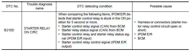
DTC Logic
DTC DETECTION LOGIC
NOTE:
-
If DTC B210D is displayed with DTC U1000, first perform the trouble diagnosis for DTC U1000. Refer to SEC-29, "DTC Logic".
-
If DTC B210D is displayed with DTC U1010, first perform the trouble diagnosis for DTC U1010. Refer to SEC-30, "DTC Logic"
-
If DTC B210D is displayed with DTC B2617, first perform the trouble diagnosis for DTC B2617. Refer to SEC-67, "DTC Logic".
DTC CONFIRMATION PROCEDURE
1.PERFORM DTC CONFIRMATION PROCEDURE
-
Ignition switch ON under the following conditions and wait for at least 1 second.
-
CVT selector lever is in the P (Park) or N (Neutral) position
-
Do not depress the brake pedal
-
-
Check "Self-diagnostic result" with CONSULT.
Diagnosis Procedure
Regarding Wiring Diagram information, refer to SEC-147, "Wiring Diagram".
1. PERFORM SELF DIAGNOSTIC RESULT
Perform Self Diagnostic Result of IPDM E/R using CONSULT.
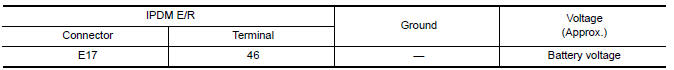
2.CHECK STARTER CONTROL RELAY CONTROL CIRCUITS VOLTAGE
Check voltage between IPDM E/R connectors and ground.
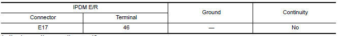
3.CHECK STARTER CONTROL RELAY CONTROL CIRCUIT CONTINUITY
-
Disconnect IPDM E/R connectors E17 and BCM connector M21.
-
Check continuity between IPDM E/R connector E17 and ground.
 B210C starter control relay
DTC Logic
DTC DETECTION LOGIC
NOTE:
If DTC B210C is displayed with DTC
U1000, first perform the trouble diagnosis for DTC U1000. Refer to
SEC-29, "DTC Logic".
If DTC B210C is di ...
 B210E starter relay
DTC Logic
DTC DETECTION LOGIC
NOTE:
If DTC B210E is displayed with DTC
U1000, first perform the trouble diagnosis for DTC U1000. Refer to
SEC-29, "DTC Logic".
If DTC B210E is di ...
Other materials:
Key slot
Description
Detects whether Intelligent Key is inserted.
Immobilizer antenna amp checks Intelligent Key transponder.
Component Function Check
1. CHECK FUNCTION
With CONSULT
Check KEY SW -SLOT in Data Monitor mode with CONSULT.
Diagnosis Procedure
1. CHECK KEY SLOT POWER SUPPLY CIRCU ...
Tel antenna
Removal and Instalation
REMOVAL
Disconnect the battery negative terminal. Refer to PG-67, "Removal
and Installation (Battery)".
Remove the rear parcel shelf finisher. Refer to INT-28, "Removal
and Installation".
Remove the Bluetooth antenna screw (A).
Detach the Bluetooth anten ...
Active noise cancellation/Active sound control (if so equipped).
Active noise cancellation
Front and rear microphones
This system uses three microphones 1 located
inside the vehicle to detect engine booming
noises. The system then automatically generates
a noise canceling sound through the speakers
and woofer to reduce engine booming noise.
NOTE:
To o ...
Nissan Maxima Owners Manual
- Illustrated table of contents
- Safety-Seats, seat belts and supplemental restraint system
- Instruments and controls
- Pre-driving checks and adjustments
- Monitor, climate, audio, phone and voice recognition systems
- Starting and driving
- In case of emergency
- Appearance and care
- Do-it-yourself
- Maintenance and schedules
- Technical and consumer information
Nissan Maxima Service and Repair Manual

0.0063