Nissan Maxima Service and Repair Manual: B210C starter control relay
DTC Logic
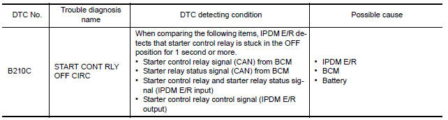
DTC DETECTION LOGIC
NOTE:
-
If DTC B210C is displayed with DTC U1000, first perform the trouble diagnosis for DTC U1000. Refer to SEC-29, "DTC Logic".
-
If DTC B210C is displayed with DTC U1010, first perform the trouble diagnosis for DTC U1010. Refer to SEC-30, "DTC Logic".
-
When IPDM E/R power supply voltage is low (Approx. 7 - 8 V for about 1 second), the DTC B210C may be detected.
DTC CONFIRMATION PROCEDURE
1.PERFORM DTC CONFIRMATION PROCEDURE
-
Turn the power supply position to start under the following conditions and wait for at least 1 second.
-
CVT selector lever is in the P (Park) or N (Neutral) position.
-
Depress the brake pedal
-
-
Check "Self-diagnostic result" with CONSULT.
Diagnosis Procedure
Regarding Wiring Diagram information, refer to SEC-147, "Wiring Diagram".
1.PERFORM SELF DIAGNOSTIC RESULT
Perform Self Diagnostic Result of IPDM E/R using CONSULT.
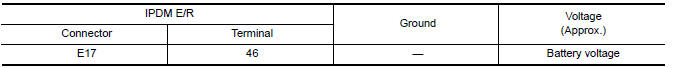
2.CHECK STARTER CONTROL RELAY CONTROL CIRCUITS VOLTAGE
Check voltage between IPDM E/R connectors and ground.
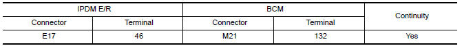
3.CHECK STARTER CONTROL RELAY CONTROL CIRCUIT CONTINUITY
-
Disconnect IPDM E/R connector E17 and BCM connector M21.
-
Check continuity between IPDM E/R connector E17 and BCM connector M21.
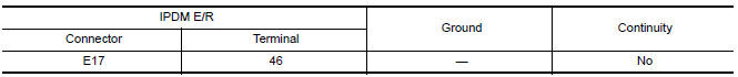
3. Check continuity between IPDM E/R connector E17 and ground.
 B210b starter control relay
DTC Logic
DTC DETECTION LOGIC
NOTE:
If DTC B210B is displayed with DTC
U1000, first perform the trouble diagnosis for DTC U1000. Refer to
SEC-29, "DTC Logic".
If DTC B210B is di ...
 B210D starter relay
DTC Logic
DTC DETECTION LOGIC
NOTE:
If DTC B210D is displayed with DTC
U1000, first perform the trouble diagnosis for DTC U1000. Refer to
SEC-29, "DTC Logic".
If DTC B210D is di ...
Other materials:
P0196 EOT sensor
Description
The engine oil temperature sensor is used to detect the engine oil
temperature. The sensor modifies a voltage signal from the ECM.
The modified signal returns to the ECM as the engine oil temperature
input. The sensor uses a thermistor which is sensitive to the
change in te ...
Steering gear and linkage
Exploded View
Outer socket
Boot clamp
Boot
Inner socket
Boot clamp
SSPS valve (part of gear assembly)
Gear assembly Front Three Bond 1111B or equivalent
Disassembly
Remove outer socket locknut and outer socket.
Remove boot clamps and boot. CAUTION:
Do not reuse boot ...
Additional service when replacing TCM
Description
When replacing the TCM, perform the following work.
TCM PROGRAMMING
Since vehicle specifications are not yet written in a new TCM, it
is necessary to write them with CONSULT.
CAUTION:
When replacing TCM, save TCM data on CONSULT before removing TCM.
LOADING AND STORIN ...
Nissan Maxima Owners Manual
- Illustrated table of contents
- Safety-Seats, seat belts and supplemental restraint system
- Instruments and controls
- Pre-driving checks and adjustments
- Monitor, climate, audio, phone and voice recognition systems
- Starting and driving
- In case of emergency
- Appearance and care
- Do-it-yourself
- Maintenance and schedules
- Technical and consumer information
Nissan Maxima Service and Repair Manual

0.0055