Nissan Maxima Service and Repair Manual: B210b starter control relay
DTC Logic
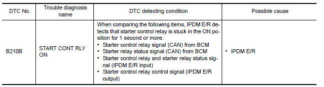
DTC DETECTION LOGIC
NOTE:
-
If DTC B210B is displayed with DTC U1000, first perform the trouble diagnosis for DTC U1000. Refer to SEC-29, "DTC Logic".
-
If DTC B210B is displayed with DTC U1010, first perform the trouble diagnosis for DTC U1010. Refer to SEC-30, "DTC Logic".
DTC CONFIRMATION PROCEDURE
1.PERFORM DTC CONFIRMATION PROCEDURE
-
Turn the power supply position to start under the following conditions and wait for at least 1 second.
-
CVT selector lever is in the P (Park) or N (Neutral) position.
-
Depress the brake pedal
-
-
Check "Self-diagnostic result" with CONSULT.
Diagnosis Procedure
1.INSPECTION START
Perform Self Diagnostic Result of IPDM E/R using CONSULT.
 B2617 starter relay circuit
Description
Located in IPDM E/R, it runs the starter motor. The
starter relay is turned ON by the BCM when the ignition
switch is in START position. IPDM E/R transmits the starter relay ON signal ...
 B210C starter control relay
DTC Logic
DTC DETECTION LOGIC
NOTE:
If DTC B210C is displayed with DTC
U1000, first perform the trouble diagnosis for DTC U1000. Refer to
SEC-29, "DTC Logic".
If DTC B210C is di ...
Other materials:
P0443 evap canister purge volume control solenoid valve
Description
The EVAP canister purge volume control solenoid valve is used to
control the flow rate of fuel vapor from the EVAP canister. The EVAP
canister purge volume control solenoid valve is moved by ON/OFF
pulses from the ECM. The longer the ON pulse, the greater the
amount of fuel ...
Outside key antenna
Description
Detects whether Intelligent Key is outside the vehicle.
Integrated in front outside handle (driver side, passenger side) and installed
in rear bumper.
Component Function Check
NOTE:
The Signal Tech II Tool (J-50190) can be used to perform the following
functions. Refer to t ...
B2603 shift position status
Description
BCM confirms the shift position with the following 2
signals.
CVT selector lever
P/N position switch
DTC Logic
DTC DETECTION LOGIC
NOTE:
If DTC B2603 is displayed with DTC
U1000, first perform the trouble diagnosis for DTC U1000. Refer to
...
Nissan Maxima Owners Manual
- Illustrated table of contents
- Safety-Seats, seat belts and supplemental restraint system
- Instruments and controls
- Pre-driving checks and adjustments
- Monitor, climate, audio, phone and voice recognition systems
- Starting and driving
- In case of emergency
- Appearance and care
- Do-it-yourself
- Maintenance and schedules
- Technical and consumer information
Nissan Maxima Service and Repair Manual

0.0065