Nissan Maxima Service and Repair Manual: B2603 shift position status
Description
BCM confirms the shift position with the following 2 signals.
-
CVT selector lever
-
P/N position switch
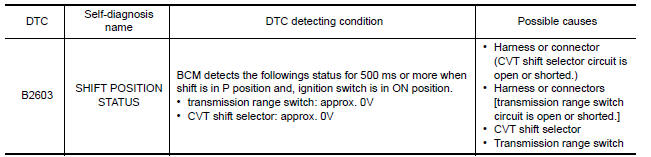
DTC Logic
DTC DETECTION LOGIC
NOTE:
-
If DTC B2603 is displayed with DTC U1000, first perform the trouble diagnosis for DTC U1000. Refer to SEC-29, "DTC Logic".
-
If DTC B2603 is displayed with DTC U1010, first perform the trouble diagnosis for DTC U1010. Refer to SEC-30, "DTC Logic".
DTC CONFIRMATION PROCEDURE
1.PERFORM DTC CONFIRMATION PROCEDURE
-
Start the engine under the following conditions and wait for at least 1 second.
-
CVT selector lever is in the P position.
-
Do not depress the brake pedal.
-
-
Shift to N and wait for at least 1 second.
-
Shift to any gear other than P or N and wait for at least 1 second.
-
Check "Self diagnostic result" with CONSULT.
Diagnosis Procedure
Regarding Wiring Diagram information, refer to SEC-147, "Wiring Diagram" or SEC-128, "Wiring Diagram".
1.CHECK DTC WITH IPDM E/R
Check "Self diagnostic result" with CONSULT. Refer to PCS-27, "DTC Index".
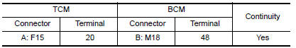
2.CHECK TRANSMISSION RANGE SWITCH CIRCUIT
-
Turn ignition switch OFF.
-
Disconnect TCM harness connector and BCM harness connector.
-
Check continuity between TCM harness connector F15 (A) terminal 20 and BCM harness connector M18 (B) terminal 48.
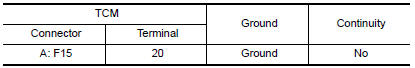
4. Check continuity between TCM harness connector F15 (A) terminal 20 and ground.
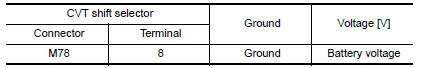
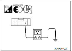
3.CHECK CVT SHIFT SELECT POWER SUPPLY
-
Turn ignition switch OFF.
-
Disconnect CVT shift selector harness connector.
-
Check voltage between CVT shift selector harness connector M78 terminal 8 and ground.
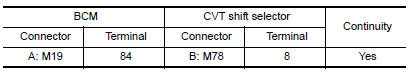
4.CHECK CVT SHIFT SELECTOR POWER SUPPLY CIRCUIT
-
Disconnect BCM harness connector.
-
Check continuity between BCM harness connector M19 (A) terminal 84 and CVT shift selector harness connector M78 (B) terminal 8.
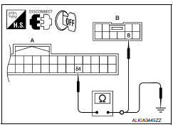
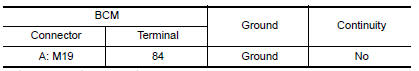
3. Check continuity between BCM harness connector M19 (A) terminal 84 and ground.
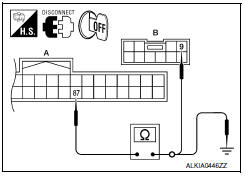
5.CHECK CVT SHIFT SELECTOR CIRCUIT
-
Disconnect BCM harness connector.
-
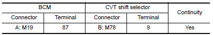
Check continuity between BCM harness connector M19 (A) terminal 87 and CVT shift selector harness connector M78 (B) terminal 9.
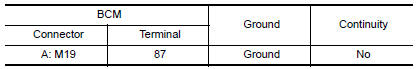
3. Check continuity between BCM harness connector M19 (A) terminal 87 and ground.
6.CHECK CVT SHIFT SELECTOR
Refer to SEC-52, "Component Inspection".
7.CHECK INTERMITTENT INCIDENT
Refer to GI-41, "Intermittent Incident".
Inspection End.
 B2602 shift position
Description
BCM confirms the shift position with the following 2
signals.
CVT selector lever
Speed signal from meter
DTC Logic
DTC DETECTION LOGIC
NOTE:
If ...
 B2604 transmission range switch
Description
BCM confirms the shift position with the following 4
signals.
CVT selector lever
Transmission range switch
P position signal from IPDM E/R (CAN) ...
Other materials:
Audio unit
Reference Value
TERMINAL LAYOUT
PHYSICAL VALUES
...
Recommended fluids/lubricants and capacities
The following are approximate capacities. The actual refill capacities may
be slightly different. When refilling, follow the procedure
described in the "Do-it-yourself" section to determine the proper refill
capacity.
...
Checking engine coolant level
Check the coolant level in the reservoir when
the engine is cold. If the coolant level is below
the MIN level B , add coolant to the MAX level
A . If the reservoir is empty, check the coolant
level in the radiator when the engine is cold. If
there is insufficient coolant in the radiator, fi ...
Nissan Maxima Owners Manual
- Illustrated table of contents
- Safety-Seats, seat belts and supplemental restraint system
- Instruments and controls
- Pre-driving checks and adjustments
- Monitor, climate, audio, phone and voice recognition systems
- Starting and driving
- In case of emergency
- Appearance and care
- Do-it-yourself
- Maintenance and schedules
- Technical and consumer information
Nissan Maxima Service and Repair Manual

0.0065