Nissan Maxima Service and Repair Manual: B2602 shift position
Description
BCM confirms the shift position with the following 2 signals.
-
CVT selector lever
-
Speed signal from meter
DTC Logic
DTC DETECTION LOGIC
NOTE:
-
If DTC B2602 is displayed with DTC U1000, first perform the trouble diagnosis for DTC U1000. Refer to SEC-29, "DTC Logic".
-
If DTC B2602 is displayed with DTC U1010, first perform the trouble diagnosis for DTC U1010. Refer to SEC-30, "DTC Logic".
DTC CONFIRMATION PROCEDURE
1.PERFORM DTC CONFIRMATION PROCEDURE
-
Start the engine under the following conditions and wait for at least 10 seconds.
-
CVT selector lever is in the P or N position
-
Depress the brake pedal.
-
-
Drive the vehicle for at least 10 seconds at a speed greater than 4 km/h (2 MPH).
-
Check "Self diagnostic result" with CONSULT.
Diagnosis Procedure
Regarding Wiring Diagram information, refer to SEC-147, "Wiring Diagram" or SEC-128, "Wiring Diagram".
1.CHECK DTC WITH "COMBINATION METER"
Check "Self diagnostic result" with CONSULT. Refer to PCS-27, "DTC Index".
2.CHECK CVT SHIFT SELECTOR POWER SUPPLY
-
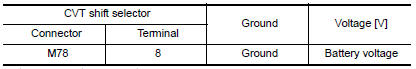
Turn ignition switch to ACC.
-
Disconnect CVT shift selector harness connector.
-
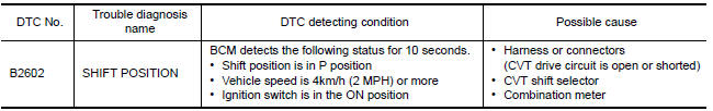
Check voltage between CVT shift selector harness connector M78 terminal 8 and ground.
3.CHECK CVT SHIFT SELECTOR POWER SUPPLY CIRCUIT
-
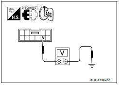
Disconnect BCM harness connector.
-
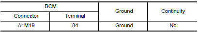
Check continuity between BCM harness connector M19 (A) terminal 84 and CVT shift selector harness connector M78 (B) terminal 8.
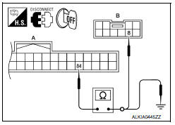
3. Check continuity between BCM harness connector M19 (A) terminal 84 and ground.
4.CHECK CVT SHIFT SELECTOR CIRCUIT
-
Disconnect BCM harness connector.
-
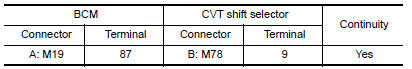
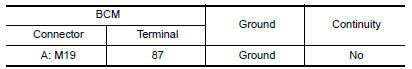
Check continuity between CVT shift selector harness connector M78 (B) terminal 9 and BCM harness connector M19 (A) terminal 87.
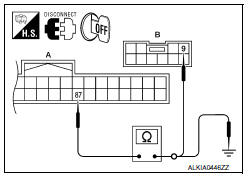
3. Check continuity between BCM harness connector M19 (A) terminal 87 and ground.
5.CHECK CVT SHIFT SELECTOR
Refer to SEC-52, "Component Inspection".
6.CHECK INTERMITTENT INCIDENT
Refer to GI-41, "Intermittent Incident".
Inspection End.
 B2601 shift position
Description
BCM confirms the shift position with the following 2
signals.
CVT selector lever
P position signal from IPDM E/R (CAN)
DTC Logic
DTC DETECTION LOGIC
N ...
 B2603 shift position status
Description
BCM confirms the shift position with the following 2
signals.
CVT selector lever
P/N position switch
DTC Logic
DTC DETECTION LOGIC
NOTE:
If DTC ...
Other materials:
Battery replacement
CAUTION
Be careful not to allow children to swallow
the battery or removed parts.
NISSAN Intelligent Key
Replace the battery in the Intelligent Key as follows:
1. Remove the mechanical key from the Intelligent
Key.
2. Insert a small flathead screwdriver A into
the slit B of the corner ...
Audio system
Symptom Table
AUDIO SYSTEM
RELATED TO HANDS-FREE PHONE
Before performing diagnosis, confirm that the cellular phone being
used by the customer is compatible with
the vehicle.
It is possible that a malfunction is occurring due to a version
change of the phone even tho ...
System operation
The automatic drive positioner system will not
work or will stop operating under the following
conditions:
When the vehicle speed is above 0 mph
(0 km/h) or 4 mph (7km/h) for some limited
functions such as linking a key fob to the
meter when the power source is turned on
from off or du ...
Nissan Maxima Owners Manual
- Illustrated table of contents
- Safety-Seats, seat belts and supplemental restraint system
- Instruments and controls
- Pre-driving checks and adjustments
- Monitor, climate, audio, phone and voice recognition systems
- Starting and driving
- In case of emergency
- Appearance and care
- Do-it-yourself
- Maintenance and schedules
- Technical and consumer information
Nissan Maxima Service and Repair Manual

0.0066