Nissan Maxima Service and Repair Manual: Sunload sensor
Removal and Installation
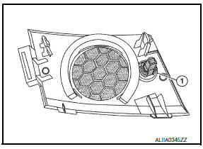
REMOVAL
- Remove the front LH speaker grille from the instrument panel. Refer to IP-10, "Exploded View".
- Disconnect the harness connector from the sunload sensor.
- Release the sunload sensor tabs and remove the sunload sensor (1) from the front LH speaker grille.
INSTALLATION
Installation is in the reverse order of removal.
 In-vehicle sensor
Removal and Installation
REMOVAL
Remove the instrument lower panel LH. Refer to IP-19, "Removal and
Installation".
Remove the in-vehicle sensor screw and the in-vehicle sensor. ...
 Intake sensor
Removal and Installation
REMOVAL
Remove the evaporator (2). Refer to HA-48, "EVAPORATOR:
Removal and Installation".
Release the intake sensor clip (A), then remove the intake sensor ...
Other materials:
B2578, B2579 in-vehicle sensor
Description
In-vehicle Sensor
The in-vehicle sensor (1) is located on instrument lower cover
(LH).
It converts variations in compartment air temperature drawn from
the aspirator into a resistance value. It is then input into the A/C
auto amp.
In-vehicle Sensor Circuit
Aspira ...
Inside mirror
Exploded View
Inside mirror
Inside mirror finisher
Mirror base
Removal and Installation
REMOVAL
Remove inside mirror finisher.
Remove screw of mirror base.
Slide the mirror upward to remove.
Disconnect the harness connector from the inside mirror.
INSTALLATION
Ins ...
Variable induction air system
System Diagram
System Description
INPUT/OUTPUT SIGNAL CHART
*: ECM determines the start signal status by the signals of engine speed and
battery voltage.
SYSTEM DESCRIPTION
In the medium speed range, the power valves are closed. Under this condition,
the pressure waves of the
...
Nissan Maxima Owners Manual
- Illustrated table of contents
- Safety-Seats, seat belts and supplemental restraint system
- Instruments and controls
- Pre-driving checks and adjustments
- Monitor, climate, audio, phone and voice recognition systems
- Starting and driving
- In case of emergency
- Appearance and care
- Do-it-yourself
- Maintenance and schedules
- Technical and consumer information
Nissan Maxima Service and Repair Manual

0.0061