
Nissan Maxima Service and Repair Manual: Intake sensor
Removal and Installation
REMOVAL
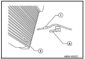
- Remove the evaporator (2). Refer to HA-48, "EVAPORATOR: Removal and Installation".
- Release the intake sensor clip (A), then remove the intake sensor (1).
CAUTION:
- Mark the mounting position of the intake sensor.
- Do not damage the evaporator core.
INSTALLATION
Installation is in the reverse order of removal.
 Sunload sensor
Removal and Installation
REMOVAL
Remove the front LH speaker grille from the instrument panel.
Refer to IP-10, "Exploded View".
Disconnect the harness connector from the sunload se ...
 Refrigerant pressure sensor
Removal and Installation
REMOVAL
Discharge the refrigerant. Refer to HA-28, "Recycle Refrigerant".
Remove the core support upper cover.
Disconnect the harness connector from the ref ...
Other materials:
Main line between ADP and DLC circuit
Diagnosis Procedure
1.CHECK CONNECTOR
Turn the ignition switch OFF.
Disconnect the battery cable from the negative terminal.
Check the following terminals and connectors for damage, bend and
loose connection (connector side
and harness side).
Harness connector B1
Harness connect ...
Antenna AMP.
Removal and Installation
REMOVAL
Remove the rear pillar finisher RH. Refer to INT-36, "Exploded
View".
Detach the antenna amp. harness clip (A).
Disconnect the harness connectors (B) from the antenna amp.
(1).
Remove the antenna amp. screw (C) and the antenna amp. (1).
...
Door outside molding
Exploded View
Front door sash molding
Front door outside molding
Rear door outside molding
Rear door sash molding (lower)
Rear door sash molding (upper)
Pawl
Removal and Installation
FRONT DOOR OUTSIDE MOLDING
Removal
Open the front door window fully.
Remove the ...
Nissan Maxima Owners Manual
- Illustrated table of contents
- Safety-Seats, seat belts and supplemental restraint system
- Instruments and controls
- Pre-driving checks and adjustments
- Monitor, climate, audio, phone and voice recognition systems
- Starting and driving
- In case of emergency
- Appearance and care
- Do-it-yourself
- Maintenance and schedules
- Technical and consumer information
Nissan Maxima Service and Repair Manual

0.0118