Nissan Maxima Service and Repair Manual: Front bumper
Exploded View
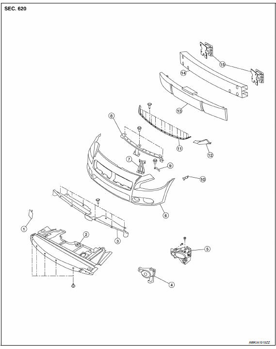
- Tow cover
- Engine under cover
- Core support cover
- Fog lamp cover
- Fog lamp (if equipped)
- Front bumper fascia
- Center support bracket
- Upper fascia support
- Front bumper upper bracket
- Front bumper side bracket
- Front bumper fascia seal
- Front bumper stiffener
- Front energy absorber
- Front bumper reinforcement
- Front bumper supports (RH/LH)
Removal and Installation
REMOVAL
- Release the core support cover clips, then remove the core support cover.
- Release the engine under cover clips, then remove engine under cover.
- Remove the front fender protector side covers (RH/LH). Refer to EXT-24, "Removal and Installation".
- Remove both front fender protectors clips and screws from the front edge and partially remove, moving the protectors as necessary for access.
- Remove the front bumper fascia clips and screws, then remove front bumper fascia.
- Remove the fog lamps (if equipped). Refer to EXL-156, "Removal and Installation".
- Remove the front grille. Refer to EXT-19, "Removal and Installation".
- Remove the front energy absorber.
- Disconnect the harness connector, then remove the ambient temperature sensor.
- Remove the upper fascia support bolts, then remove upper fascia support.
- Remove the front bumper reinforcement bolts, then remove front bumper reinforcement.
- Remove the front bumper support bolts, then remove the front bumper supports (RH/LH).
INSTALLATION
Installation is in the reverse order of removal.

 Rear bumper
Exploded View
Rear bumper supports (RH/LH)
Rear bumper reinforcement
Rear energy absorber
Side bracket (RH/LH)
Rear bumper fascia
Removal and Installation
REMOVAL
Remove trunk ...
Other materials:
P1777 step motor
Description
The step motor changes the step by turning 4 coils ON/OFF
according to the signal from TCM. As a result, the
flow of line pressure to primary pulley is changed and pulley ratio is
controlled.
DTC Logic
DTC DETECTION LOGIC
DTC CONFIRMATION PROCEDURE
CAUTION:
Always drive ve ...
U1000 CAN comm circuit
Description
CAN (Controller Area Network) is a serial communication line for real time
application. It is an on-vehicle multiplex
communication line with high data communication speed and excellent error
detection ability. Many electronic
control units are equipped onto a vehicle and each c ...
Sound signal circuit
SATELLITE RADIO TUNER
SATELLITE RADIO TUNER : Description
Left and right channel audio signals are supplied from the satellite radio
tuner to the AV control unit through the sound signal circuits.
SATELLITE RADIO TUNER : Diagnosis Procedure
LEFT CHANNEL
1.CHECK HARNESS
Turn ignition swi ...
Nissan Maxima Owners Manual
- Illustrated table of contents
- Safety-Seats, seat belts and supplemental restraint system
- Instruments and controls
- Pre-driving checks and adjustments
- Monitor, climate, audio, phone and voice recognition systems
- Starting and driving
- In case of emergency
- Appearance and care
- Do-it-yourself
- Maintenance and schedules
- Technical and consumer information
Nissan Maxima Service and Repair Manual

0.0056