Nissan Maxima Service and Repair Manual: Wiring diagram
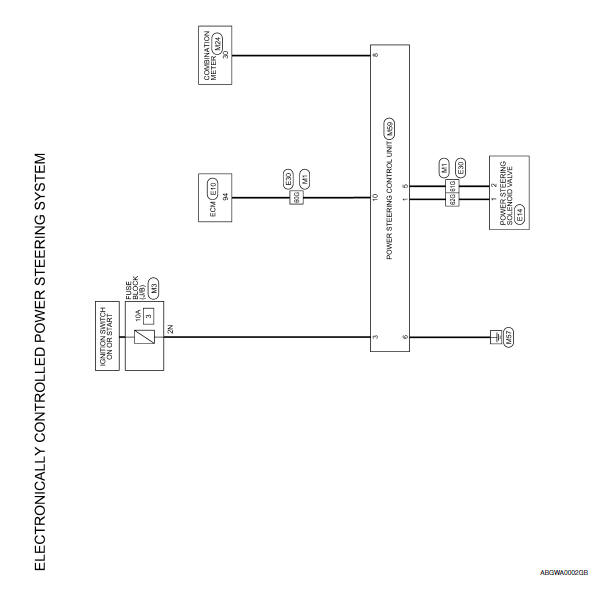
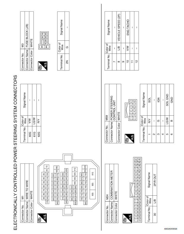
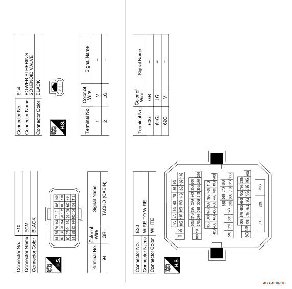
ELECTRONICALLY CONTROLLED POWER STEERING SYSTEM
Wiring Diagram
 ECU diagnosis information
POWER STEERING CONTROL UNIT
Reference Value
TERMINA LAYOUT
PHYSICAL VALUES
CAUTION: When using circuit tester or oscilloscope to
measure voltage for inspection, be sure not to extend forcibl ...
 Symptom diagnosis
UNBALANCE STEERING WHEEL TURNING FORCE (TORQUE VARIATION)
Description
Hard steering when fully turning the steering wheel.
Light steering when driving at a high speed.
Diagnosis Procedure
1 ...
Other materials:
Precaution
PRECAUTIONS
Precaution for Supplemental Restraint System (SRS) "AIR BAG" and
"SEAT BELT PRE-TENSIONER"
The Supplemental Restraint System such as "AIR BAG" and "SEAT BELT
PRE-TENSIONER", used along with a front seat belt, helps to reduce the risk
or severity of injury to the driver and front ...
Preparation
Special Service Tool
The actual shapes of the tools may differ from those illustrated her
Commercial Service Tool
...
Moving Object Detection (MOD) (if so equipped)
1. CAMERA button
WARNING
Failure to follow the warnings and instructions
for proper use of the Moving
Object Detection system could result in
serious injury or death.
The MOD system is not a substitute for
proper vehicle operation and is not designed
to prevent contact with obje ...
Nissan Maxima Owners Manual
- Illustrated table of contents
- Safety-Seats, seat belts and supplemental restraint system
- Instruments and controls
- Pre-driving checks and adjustments
- Monitor, climate, audio, phone and voice recognition systems
- Starting and driving
- In case of emergency
- Appearance and care
- Do-it-yourself
- Maintenance and schedules
- Technical and consumer information
Nissan Maxima Service and Repair Manual

0.0058