Nissan Maxima Service and Repair Manual: P1217 engine over temperature
DTC Logic
DTC DETECTION LOGIC
NOTE:
- If DTC P1217 is displayed with DTC UXXXX, first perform the
trouble diagnosis for DTC UXXXX.
Refer to EC-161, "DTC Logic".
- If DTC P1217 is displayed with DTC P0607, first perform the trouble diagnosis for DTC P0607. Refer to EC-393, "DTC Logic".
If the cooling fan or another component in the cooling system malfunctions, engine coolant temperature will rise.
When the engine coolant temperature reaches an abnormally high temperature condition, a malfunction is indicated.
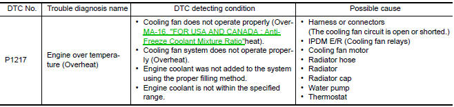
CAUTION: When a malfunction is indicated, always replace the coolant. Refer to CO-10, "System Inspection".
Also, replace the engine oil. Refer to MA-23, "ENGINE OIL : Changing Engine Oil".
- Fill radiator with coolant up to specified level with a filling speed of 2 liters per minute. Always use coolant with the proper mixture ratio. Refer to MA-16, "FOR USA AND CANADA : Anti-Freeze Coolant Mixture Ratio" (For NORTH AMERICA) or MA-17, "FOR MEXICO : Engine Coolant Mixture Ratio" (For MEXICO).
- After refilling coolant, run engine to ensure that no water-flow noise is emitted.
DTC CONFIRMATION PROCEDURE
1.PERFORM COMPONENT FUNCTION CHECK
Perform component function check. Refer to EC-406, "Component Function Check".
NOTE: Use component function check to check the overall function of the cooling fan. During this check, a DTC might not be confirmed.
Component Function Check
1.PERFORM COMPONENT FUNCTION CHECK-I
WARNING: Never remove the radiator cap when the engine is hot. Serious burns could be caused by high pressure fluid escaping from the radiator.
Wrap a thick cloth around cap. Carefully remove the cap by turning it a quarter turn to allow built-up pressure to escape. Then turn the cap all the way off.
Check the coolant level in the reservoir tank and radiator.
Allow engine to cool before checking coolant level.
2.PERFORM COMPONENT FUNCTION CHECK-II
Confirm whether customer filled the coolant or not.
3.PERFORM COMPONENT FUNCTION CHECK-III
With CONSULT
- Turn ignition switch ON.
- Perform "COOLING FAN" in "ACTIVE TEST" mode with CONSULT.
- Check that cooling fan motors-1 and -2 operate at each speed (LOW/MID/HI).
Without CONSULT
Perform IPDM E/R auto active test and check cooling fan motors operation
Diagnosis Procedure
1.CHECK COOLING FAN OPERATION
With CONSULT
- Turn ignition switch ON.
- Perform "COOLING FAN" in "ACTIVE TEST" mode with CONSULT.
- Check that cooling fans-1 and -2 operate at each speed (LOW/MID/HI).
Without CONSULT
- Perform IPDM E/R auto active test and check cooling fan motors operation, refer to PCS-11, "Diagnosis Description".
- Check that cooling fans-1 and -2 operate at each speed (Low/Middle/High).
2.CHECK COOLING SYSTEM FOR LEAKAGE-I
Check cooling system for leakage
3.CHECK COOLING SYSTEM FOR LEAKAGE-II
Check the following for leakage.
- Hose
- Radiator
- Water pump
4.CHECK RADIATOR CAP
Check radiator cap
5.CHECK THERMOSTAT
Check thermostat.
6.CHECK ENGINE COOLANT TEMPERATURE SENSOR
7.CHECK MAIN 12 CAUSES
If the cause cannot be isolated, check the following.
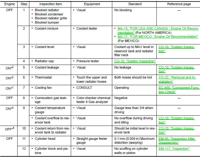
*1: Turn the ignition switch ON.
*2: Engine running at 3,000 rpm for 10 minutes
*3: Drive at 90 km/h (56 MPH) for 30 minutes and then let idle for 10 minutes.
*4: After 60 minutes of cool down time
 P1212 TCS communication line
Description
This CAN communication line is used to control the smooth engine operation
during the TCS operation. Pulse
signals are exchanged between ECM and "ABS actuator and electric unit (contr ...
 P1225 TP sensor
Description
Electric throttle control actuator consists of throttle control motor,
throttle position sensor, etc. The throttle position sensor responds to
the throttle valve movement.
The ...
Other materials:
License lamp finisher
Exploded View
License lamp finisher
Trunk request switch connector
Grommet Clip
Removal and Installat
REMOVAL
Remove the trunk lid finisher. Refer to INT-36, "Removal and
Installation".
Disconnect the harness connector (1) from the trunk request
switch.
Remove the ...
Excessive ABS function operation frequency
Diagnosis Procedure
1.CHECK START
Check front and rear brake force distribution using a brake tester.
2.CHECK FRONT AND REAR AXLE
Make sure that there is no excessive play in the front and rear axles.
3.CHECK WHEEL SENSOR AND SENSOR ROTOR
Check the following:
Wheel sensor installation for ...
Disk eject signal circuit
Description
The eject signal is output to AV control unit when the eject switch of A/C
and AV switch assembly is pressed.
Diagnosis Procedure
1.CHECK CONTINUITY DISK EJECT SIGNAL CIRCUIT
Turn ignition switch OFF.
Disconnect A/C and AV switch assembly connector M98 and AV
control un ...
Nissan Maxima Owners Manual
- Illustrated table of contents
- Safety-Seats, seat belts and supplemental restraint system
- Instruments and controls
- Pre-driving checks and adjustments
- Monitor, climate, audio, phone and voice recognition systems
- Starting and driving
- In case of emergency
- Appearance and care
- Do-it-yourself
- Maintenance and schedules
- Technical and consumer information
Nissan Maxima Service and Repair Manual

0.0059