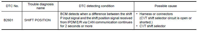
Nissan Maxima Service and Repair Manual: B2601 shift position
Description
BCM confirms the shift position with the following 2 signals.
-
CVT selector lever
-
P position signal from IPDM E/R (CAN)
DTC Logic
DTC DETECTION LOGIC
NOTE:
-
If DTC B2601 is displayed with DTC U1000, first perform the trouble diagnosis for DTC U1000. Refer to SEC-29, "DTC Logic".
-
If DTC B2601 is displayed with DTC U1010, first perform the trouble diagnosis for DTC U1010. Refer to SEC-30, "DTC Logic".
-
If DTC B2601 is displayed with DTC B2605, first perform the trouble diagnosis for DTC B2605. Refer to SEC-61, "DTC Logic".
DTC CONFIRMATION PROCEDURE
1.PERFORM DTC CONFIRMATION PROCEDURE
-
Turn ignition switch ON under the following conditions, and wait for at least 2 seconds.
-
CVT selector lever is in the P position.
-
Do not depress the brake pedal.
-
-
Check "Self diagnostic result" with CONSULT.
-
Turn ignition switch ON under the following conditions, and wait for at least 2 seconds.
-
CVT selector lever is in other than P position.
-
Do not depress the brake pedal.
-
-
Check "Self diagnostic result" with CONSULT.
Diagnosis Procedure
Regarding Wiring Diagram information, refer to SEC-147, "Wiring Diagram" or SEC-128, "Wiring Diagram".
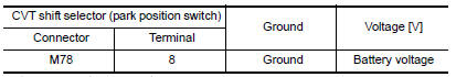
1.CHECK CVT SHIFT SELECTOR POWER SUPPLY
-
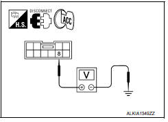
Turn ignition switch to ACC.
-
Disconnect CVT shift selector harness connector.
-
Check voltage between CVT shift selector harness connector M78 terminal 8 and ground.
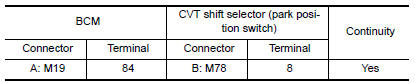
2.CHECK CVT SHIFT SELECTOR POWER SUPPLY CIRCUIT
-
Disconnect BCM harness connector.
-
Check continuity between BCM harness connector M19 (A) terminal 84 and CVT shift selector harness connector M78 (B) terminal 8.
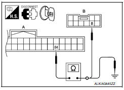
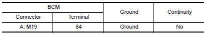
3. Check continuity between BCM harness connector M19 (A) terminal 84 and ground.
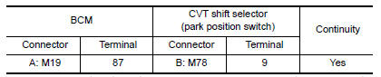
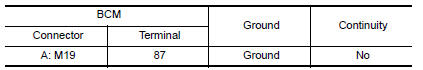
3.CHECK CVT SHIFT SELECTOR CIRCUIT (BCM)
-
Disconnect BCM harness connector and IPDM E/R harness connector.
-
Check continuity between BCM harness connector M19 (A) terminal 87 and CVT shift selector harness connector M78 (B) terminal 9.
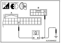
3. Check continuity between BCM harness connector M19 (A) terminal 87 and ground.
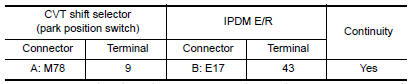
4.CHECK CVT SHIFT SELECTOR CIRCUIT (IPDM E/R)
-
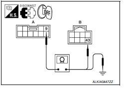
Disconnect IPDM E/R harness connector.
-
Check continuity between CVT shift selector harness connector M78 (A) terminal 9 and IPDM E/R harness connector E17 (B) terminal 43.
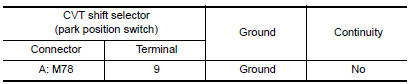
3. Check continuity between CVT shift selector harness connector M78 (A) terminal 9 and ground.
5.CHECK CVT SHIFT SELECTOR
Refer to SEC-52, "Component Inspection".
6.CHECK INTERMITTENT INCIDENT
Refer to GI-41, "Intermittent Incident".
Inspection End.
Component Inspection
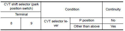
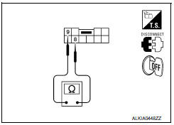
1.CHECK CVT SHIFT SELECTOR
-
Turn ignition switch OFF.
-
Disconnect CVT shift selector harness connector.
-
Check continuity between CVT shift selector terminals as follows.
 B2560 starter control relay
Description
Starter control relay, integrated in IPDM E/R, permits
the starter relay operation when in N or P position. It is
installed in parallel with the starter relay.
DTC Logic
DTC DETECTI ...
 B2602 shift position
Description
BCM confirms the shift position with the following 2
signals.
CVT selector lever
Speed signal from meter
DTC Logic
DTC DETECTION LOGIC
NOTE:
If ...
Other materials:
Refrigerant pressure sensor
Removal and Installation
REMOVAL
Discharge the refrigerant. Refer to HA-28, "Recycle Refrigerant".
Remove the core support upper cover.
Disconnect the harness connector from the refrigerant pressure
sensor.
Remove the refrigerant pressure sensor.
CAUTION:
Cap or wrap the ...
Tire and loading information label
Seating capacity: The maximum number
of occupants that can be seated
in the vehicle.
Vehicle load limit: Refer to the loading
information in the "Technical and
consumer information" section of this
manual.
Original tire size: The size of the tires
originally installed on the v ...
Folding rear seat
Interior trunk access
The trunk can be accessed from the passenger
side of the rear seat for loading and unloading, as
shown.
1. Move the front passenger seat to the most
forward position.
2. Open the access cover on the rear parcel
shelf.
3. Push down on the button 1 on the rear
pa ...
Nissan Maxima Owners Manual
- Illustrated table of contents
- Safety-Seats, seat belts and supplemental restraint system
- Instruments and controls
- Pre-driving checks and adjustments
- Monitor, climate, audio, phone and voice recognition systems
- Starting and driving
- In case of emergency
- Appearance and care
- Do-it-yourself
- Maintenance and schedules
- Technical and consumer information
Nissan Maxima Service and Repair Manual

0.0063