Nissan Maxima Service and Repair Manual: Camshaft
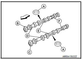
Exploded View
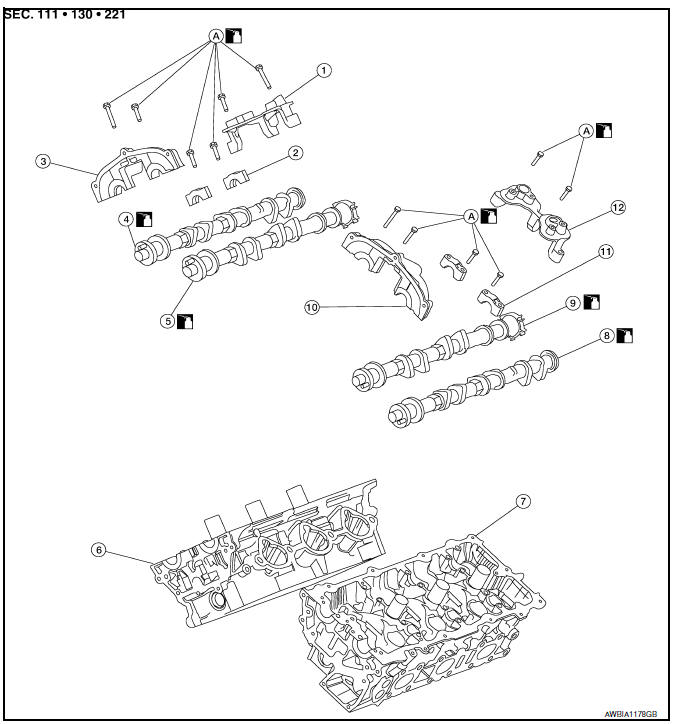
- Camshaft position sensor bracket (RH)
- Camshaft brackets
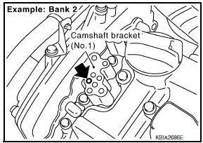
- No. 1 camshaft bracket (RH)
- Camshaft (EXH) (RH)
- Camshaft (INT) (RH)
- Cylinder head (RH)
- Cylinder head (LH)
- Camshaft (EXH) (LH)
- Camshaft (INT) (LH)
- No. 1 camshaft bracket (LH)
- Camshaft brackets
- Camshaft position sensor bracket (LH)
- Refer to INSTALLATION
CAUTION: Apply new engine oil to parts marked in illustration before installation.
Removal and Installation
REMOVAL
- Remove the timing chains.
- Remove camshaft position brackets (RH shown, LH similar).
- Remove the camshaft brackets and the camshafts.
- Mark the camshafts, camshaft brackets, and bolts so they are placed in the same position and direction for installation.
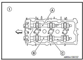
- Equally loosen the camshaft bracket bolts in several steps in the reverse order as shown.
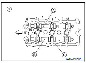
- : Cylinder head (RH)
- Camshaft (EXH) (RH)
- Camshaft (INT) (RH)
- : Camshaft bracket
 : Engine front
- Cylinder head (LH)
- : Camshaft (INT) (LH)
- Camshaft bracket
- Camshaft (EXH) (LH)
 : Engine front
Remove valve lifters, if necessary.
NOTE: Identify installation positions to ensure proper installation.
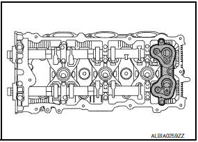
- Remove secondary timing chain tensioner from cylinder head.
- Remove secondary tensioner with its stopper pin attached.
NOTE: Stopper pin was attached when secondary timing chain was removed.
INSTALLATION
- Before installation, remove any old Silicone RTV Sealant from component mating surfaces using a scraper.
- Remove the old Silicone RTV Sealant from the bolt holes and threads.
- Do not scratch or damage the mating surfaces.
- Before installing the front cam bracket, remove the old Silicone RTV Sealant from the mating surface using a scraper.
- Do not scratch or damage the mating surface.
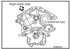
- Turn the crankshaft until No. 1 piston is set at TDC on the compression stroke.
- The crankshaft key should line up with the right bank cylinder center line as shown.
- Install camshaft chain tensioners on both sides of cylinder head.
Refer to EM-54, "Removal and Installation".
- Install valve lifters, if removed.
NOTE: Install them in original positions.
- Install exhaust and intake camshafts and camshaft brackets.
- Intake camshaft has a drill mark on camshaft sprocket mounting flange.
- Follow your identification marks made during removal, or follow the identification marks that are present on the new camshaft components for proper placement and direction of the components.
 :Engine front
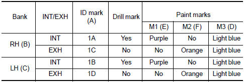
- Position the camshaft dowel pins (A) as shown.
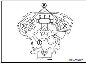
- :Crankshaft key
- Before installing camshaft brackets, apply sealant to mating surface of No. 1 camshaft bracket.
- Use Genuine Silicone RTV Sealant, or equivalent. Refer to GI-21, "Recommended Chemical Products and Sealants".
CAUTION:
- Installation should be done within 5 minutes after applying liquid gasket.
- Do not fill the engine with oil for at least 30 minutes after the components are installed to allow the sealant to cure.
- Before installation, wipe off any protruding sealant.
- Refer to EM-4, "Precaution for Liquid Gasket".
- Install camshaft brackets in their original positions and direction.
Align the stamp marks as shown.
- If checking and adjusting any part of valve assembly or camshaft, check valve clearance according to the reference data. Refer to EM-18, "Valve Clearance".
Valve clearance (cold) Intake : 0.26 - 0.34 mm (0.010 - 0.013 in)
Valve clearance (cold) Exhaust : 0.29 - 0.37 mm (0.011 - 0.015 in)
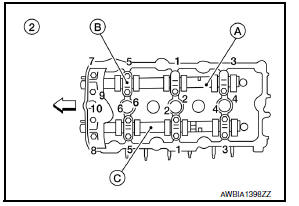
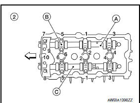
- Tighten the camshaft brackets in the three steps, in numerical order as shown.
- Cylinder head (RH)
- : Camshaft (EXH) (RH)
- : Camshaft (INT) (RH)
- : Camshaft bracket
: Engine front
- Cylinder head (LH)
- : Camshaft (INT) (LH)
- Camshaft bracket
- Camshaft (EXH) (LH)
: Engine front
- Measure difference in levels between front end faces of No. 1 camshaft bracket and cylinder head.

Standard : - 0.14 mm (- 0.0055 in)
- Install camshaft position sensors (PHASE) (RH/LH).
- Install the fuel rail and injectors. Refer to EM-43, "Removal and Installation".
- Install the timing chains. Refer to EM-64, "Removal and Installation".If measurement is outside the specified range, re-install camshaft and camshaft bracket.
Inspection After Removal
INSPECTION
Camshaft Visual Check
Check camshaft for scratches, seizure and wear. Replace if necessary.
Camshaft Runout
- Put V-block on precise flat bed and support No. 2 and No. 4 journal of camshaft as shown.
- Set dial gauges vertically to No. 3 journal as shown.
- Turn camshaft in one direction slowly by hand, measure the camshaft runout using suitable tool as shown.
- If actual runout exceeds the limit, replace the camshaft.
- Runout is the largest indicator reading after one full revolution.
Camshaft Runout
Standard : Less than 0.02 mm (0.0008 in)
Limit :
0.05 mm (0.0020 in)
Camshaft Cam Lobe Height
- Measure camshaft cam lobe height using suitable tool as shown. Refer to EM-130, "Camshaft".
- If wear has reduced the lobe height below specifications, replace the camshaft.
Camshaft Journal Clearance
Outer Diameter of Camshaft Journal
- Measure outer diameter of camshaft journal using suitable tool as shown.
Standard outer diameter No.1 : 25.935 - 25.955 mm (1.0211 - 1.0218
in)
Standard outer diameter No.2, 3, 4 : 23.445 - 23.465 mm
(0.9230 - 0.9238 in)
Inner Diameter of Camshaft Bracket
- Tighten camshaft bracket bolt with specified torque.
- Measure inner diameter (A) of camshaft bearing using suitable tool as shown.
Standard inner diameter No.1 : 26.000 - 26.021 mm (1.0236 - 1.0244
in)
Standard inner diameter No.2, 3, 4 : 23.500 - 23.521 mm
(0.9252 - 0.9260 in)
Calculation of Camshaft Journal Clearance
(Journal clearance) = (inner diameter of camshaft bracket) - (outer diameter of camshaft journal)
No.1 : 0.045 - 0.086 mm (0.0018 - 0.0034 in)
Standard No.2, 3, 4
: 0.035 - 0.076 mm (0.0014 - 0.0030 in)
Limit : 0.15 mm (0.0059 in
- When out of the specified range, replace either or both camshaft and cylinder head.
NOTICE: Inner diameter of camshaft bracket is manufactured together with cylinder head. Replace the whole cylinder head assembly.
Camshaft End Play
- Install the camshaft in the cylinder head.
- Install suitable tool in thrust direction on front end of camshaft.
Measure end play when camshaft is moved forward/backward (in direction to axis) as shown.
Standard : 0.115 - 0.188 mm (0.0045 - 0.0074 in)
Limit : 0.24 mm (0.0094
in)
- If out of the specified range, replace with new camshaft and measure again.
- If out of the specified range again, replace with new cylinder head.
Camshaft Sprocket Runout
- Put V-block on precise flat bed and support No. 2 and No. 4 journal of camshaft as shown.
- Install camshaft sprocket on camshaft.
- Measure camshaft sprocket runout using suitable tool as shown.
- If sprocket runout exceeds the limit, replace camshaft sprocket.
Runout : Less than 0.15 mm (0.0059 in)
Valve Lifter
- Check if the surface of the valve lifter has any excessive wear or cracks, replace as necessary.
Valve Lifter Clearance
Outer Diameter of Valve Lifter
- Measure the outer diameter of the valve lifter using suitable tool as shown. Refer to EM-130, "Camshaft".
- If out of the specified range, replace the valve lifter.
Valve Lifter Bore Diameter
- Measure diameter of valve lifter bore of cylinder head using suitable tool as shown. Refer to EM-130, "Camshaft".
- If out of the specified range, replace the cylinder head assembly.
Calculation of Valve Lifter Clearance
- (Valve lifter clearance) = (hole diameter for valve lifter) - (outer diameter of valve lifter) Refer to EM-130, "Camshaft".
- If out of specified range, replace either or both valve lifter and cylinder head assembly.
Inspection after Installation
INSPECTION OF CAMSHAFT SPROCKET (INT) OIL GROOVE
CAUTION:
- Perform this inspection only when DTC P0011 is detected in self-diagnostic results of CONSULT III and it is directed according to inspection procedure of EC section. Refer to EC-177, "Diagnosis Procedure".
- Check when engine is cold so as to prevent burns from any splashing engine oil.
- Check engine oil level. Refer to LU-8, "Inspection".
- Perform the following procedure so as to prevent the engine from being unintentionally started while checking.
- Release fuel pressure. Refer to EC-592, "Inspection".
- Disconnect ignition coil and injector harness connectors if practical.
- Remove intake valve timing control solenoid valve.
- Crank engine, and then make sure that engine oil comes out from
intake valve timing control solenoid valve cover oil hole.
End cranking after checking.
WARNING: Be careful not to touch rotating parts (drive belts, idler pulley, and crankshaft pulley, etc.).
CAUTION:
- Engine oil may squirt from intake valve timing control solenoid valve installation hole during cranking. Use a shop cloth to prevent engine oil from splashing on worker, engine components and vehicle.
- Do not allow engine oil to get on rubber components such as drive belts or engine mount insulators. Immediately wipe off any splashed engine oil.
- Clean oil groove between oil strainer and intake valve timing control solenoid valve if engine oil does not come out from intake valve timing control solenoid valve cover oil hole.
- Remove components between intake valve timing control solenoid valve and camshaft sprocket (INT), and then check each oil groove for clogging.
- Clean oil groove if necessary.
- After inspection, installation of the remaining components is in the reverse order of removal.
 Rear Timing Chain Case
Exploded View
Rear timing chain case
O-ring
Cylinder block
Removal and Installtion
CAUTION:
After removing timing chain, do not turn the crankshaft and
camshaft separately, or th ...
 Oil Seal
Removal and Installation of Valve Oil Seal
REMOVAL
Turn crankshaft until the cylinder requiring new oil seals is at
TDC. This will prevent valve from dropping into cylinder.
CAUTION: When r ...
Other materials:
Precaution
Precaution for Supplemental Restraint System (SRS) "AIR BAG" and
"SEAT BELT PRE-TENSIONER"
The Supplemental Restraint System such as "AIR BAG" and "SEAT BELT
PRE-TENSIONER", used along with a front seat belt, helps to reduce the risk
or severity of injury to the driver and front passenger for ...
Rear view monitor system
System Diagram
System Description
When the shift selector is in the R position, the display shows a view to the
rear of the vehicle. Lines which indicate the vehicle clearance and distances
are also displayed.
Component Parts Location
Tweeter LH M143
Tweeter RH M144
AV control ...
Precautions on seat belt usage
If you are wearing your seat belt properly adjusted
and you are sitting upright and well back in
your seat with both feet on the floor, your chances
of being injured or killed in a collision and/or the
severity of injury may be greatly reduced.
NISSAN strongly encourages you and all of yo ...
Nissan Maxima Owners Manual
- Illustrated table of contents
- Safety-Seats, seat belts and supplemental restraint system
- Instruments and controls
- Pre-driving checks and adjustments
- Monitor, climate, audio, phone and voice recognition systems
- Starting and driving
- In case of emergency
- Appearance and care
- Do-it-yourself
- Maintenance and schedules
- Technical and consumer information
Nissan Maxima Service and Repair Manual

0.0079