Nissan Maxima Service and Repair Manual: Rear Timing Chain Case
Exploded View
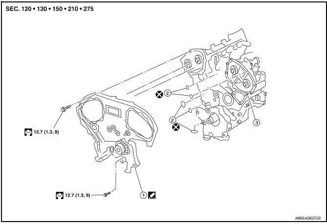
- Rear timing chain case
- O-ring
- Cylinder block
Removal and Installtion
CAUTION:
- After removing timing chain, do not turn the crankshaft and camshaft separately, or the valves will strike the pistons.
- Before removing the upper oil pan, remove the crankshaft position sensor (POS).
- Be careful not to damage sensor edges.
- Do not reuse O-ring.
REMOVAL
- Remove the engine assembly. Refer to EM-103, "Removal and Installation".
- Remove the oil pan lower and upper. Refer to EM-37, "Removal and Installation (Upper Oil Pan)".
- Remove the front timing chain case. Refer to EM-54, "Exploded View".
- Remove the timing chains (primary) and (secondary). Refer to EM-64, "Removal and Installation".
- Remove No. 1 camshaft bracket (RH) and No. 1 camshaft bracket (LH). Refer to EM-76, "Removal and Installation".
- Remove the rear timing chain case.
CAUTION:
- Do not remove the plate metal cover for the oil passage.
- After removing the chain case, do not apply any load to the case that might bend it.
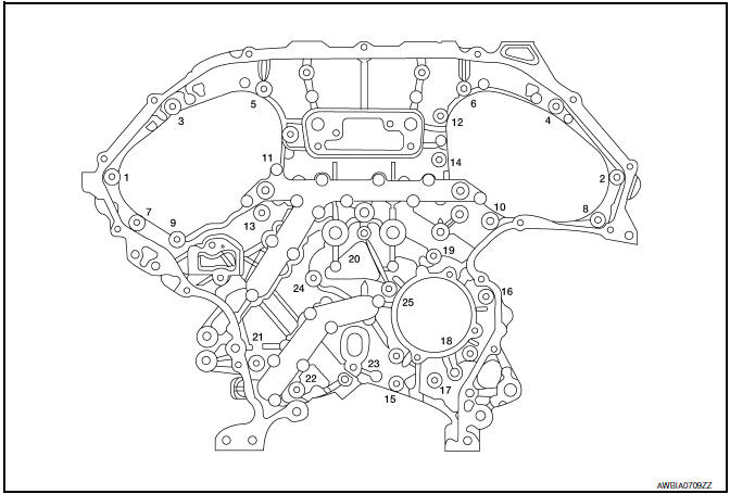
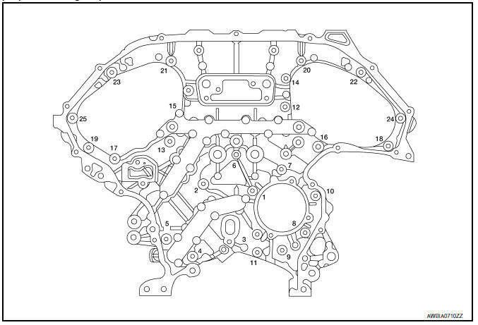
- Loosen and remove the rear timing chain case bolts in the order as shown.
- Cut the sealant using Tool and remove the rear timing chain case.
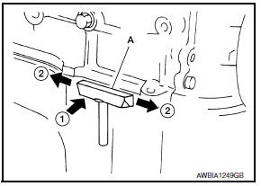
Tool number : KV10111100 (J-37228)
CAUTION:
- Be careful not to damage the mating surface.
- Do not insert a screwdriver, this will damage the mating surfaces.
- In areas where the cutter is difficult to use, use a plastic hammer to lightly tap (1) the cutter where the liquid gasket is applied. Use a plastic hammer to slide (2) the cutter by tapping on the side.
- Remove O-rings to timing chain case and cylinder block.
CAUTION: Do not reuse O-rings.
- Use a scraper to remove all of the old Silicone RTV Sealant from the front and rear timing chain case and opposite mating surfaces.
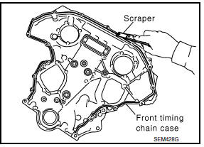
CAUTION: Do not damage the mating surfaces.
- Remove all old Silicone RTV Sealant from all the bolt holes and bolts.
CAUTION: Do not damage the threads or mating surfaces
INSTALLATION
- Install O-rings on cylinder block.
CAUTION: Do not reuse O-rings.
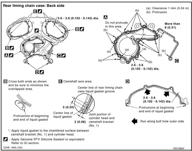
- Apply Genuine Silicone RTV Sealant or equivalent, to the rear timing
chain case using Tool as shown.
Refer to GI-21, "Recommended Chemical Products and Sealants".
Tool number : WS39930000 ( - )
CAUTION:
- For "a", completely wipe out liquid gasket extended on a portion touching at engine coolant.
- Apply liquid gasket on installation position of water pump and cylinder completely.
- Installation should be done within 5 minutes after applying liquid gasket.
- Do not fill the engine with oil for at least 30 minutes after the components are installed to allow the sealant to cure.
- Align the rear timing chain case and water pump assembly with the dowel pins (RH and LH) on the cylinder block and install the case. Make sure the O-rings stay in place during installation.
CAUTION: Do not reuse O-rings.
- Tighten the bolts in the numerical order as shown. There are two bolt lengths used. Follow the chart below for proper bolt length specifications.
- After all bolts are initially tightened, retighten them to the specification in the numerical order shown.
- Install the primary and secondary timing chains. Refer to EM-64, "Removal and Installation".
- Install the front timing chain case. Refer to EM-54, "Removal and Installation".
- Install No. 1 camshaft bracket (RH) and No. 1 camshaft bracket (LH). Refer to EM-76, "Removal and Installation".
- Install the oil pan upper and lower. Refer to EM-37, "Removal and Installation (Upper Oil Pan)".
- Install the engine assembly. Refer to EM-103, "Removal and Installation".
 Timing Chain
Exploded View
Timing chain tensioner (secondary)
Internal chain guide
Timing chain tensioner (secondary)
Camshaft sprocket (EXH)
Timing chain (secondary)
Timing chain (primary)
C ...
 Camshaft
Exploded View
Camshaft position sensor bracket (RH)
Camshaft brackets
No. 1 camshaft bracket (RH)
Camshaft (EXH) (RH)
Camshaft (INT) (RH)
Cylinder head (RH)
Cylinder head (LH)
...
Other materials:
Brake fluid
For additional information on brake fluid specification,
refer to "Recommended fluids/lubricants
and capacities" in the "Technical and consumer
information" section of this manual.
WARNING
Use only new fluid from a sealed container.
Old, inferior or contaminated
fluid may damage the ...
Rear regulator
Rear Door Glass Regulator
REMOVAL
Remove the rear door finisher. Refer to INT-21, "Removal and
Installation".
Position aside the vapor barrier.
Temporarily reconnect the power window switch and raise/lower
the door window until the glass bolts can be seen.
Remove the glass bolt ...
AV branch line circuit
Diagnosis Procedure
1.CHECK CONNECTOR
Turn the ignition switch OFF.
Disconnect the battery cable from the negative terminal.
Check the terminals and connectors of the AV control unit for
damage, bend and loose connection (unit
side and connector side).
2.CHECK HARNESS FOR OPEN CIRC ...
Nissan Maxima Owners Manual
- Illustrated table of contents
- Safety-Seats, seat belts and supplemental restraint system
- Instruments and controls
- Pre-driving checks and adjustments
- Monitor, climate, audio, phone and voice recognition systems
- Starting and driving
- In case of emergency
- Appearance and care
- Do-it-yourself
- Maintenance and schedules
- Technical and consumer information
Nissan Maxima Service and Repair Manual

0.0066