Nissan Maxima Service and Repair Manual: DTC/circuit diagnosis
SUNSHADE
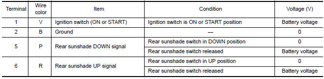
Component Parts Location
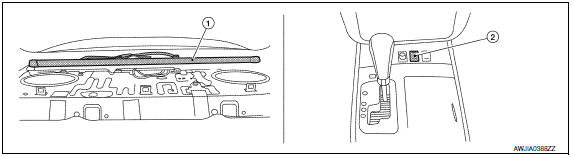
- Rear sunshade unit B22 (View with the rear parcel shelf finisher removed)
- Rear sunshade switch M308
Reference Value
 Interior
...
 Wiring diagram
REAR SUNSHADE
Wiring Diagram
...
Other materials:
Operating tips
When the engine coolant temperature and
outside air temperature are low, the air flow
from the foot outlets may not operate for a
maximum of 150 seconds. However, this is
not a malfunction. After the coolant temperature
warms up, air flow from the foot outlets
will operate normally.
...
Precaution
PRECAUTIONS
Precaution for Supplemental Restraint System (SRS) "AIR BAG" and "SEAT BELT
PRE-TENSIONER"
The Supplemental Restraint System such as "AIR BAG" and "SEAT BELT
PRE-TENSIONER", used along
with a front seat belt, helps to reduce the risk or severity of injury to the
driver and fron ...
Front tweeter
Removal and Installation
REMOVAL
Remove the front pillar finisher. Refer to INT-24, "Removal and
Installation".
Remove the front tweeter speaker grille. Refer to IP-10, "Exploded
View".
Remove the front tweeter speaker screws (A).
Pull out front tweeter speaker (1), disconnect the ...
Nissan Maxima Owners Manual
- Illustrated table of contents
- Safety-Seats, seat belts and supplemental restraint system
- Instruments and controls
- Pre-driving checks and adjustments
- Monitor, climate, audio, phone and voice recognition systems
- Starting and driving
- In case of emergency
- Appearance and care
- Do-it-yourself
- Maintenance and schedules
- Technical and consumer information
Nissan Maxima Service and Repair Manual

0.0054