Nissan Maxima Service and Repair Manual: Air breather hose
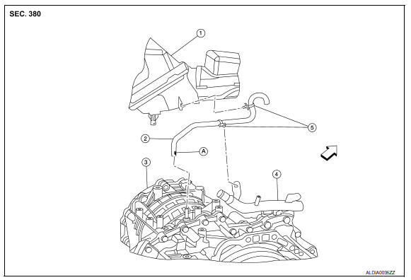
Exploded View
-
Air cleaner case
-
Air breather hose
-
Transaxle assembly
-
Heater pipe
-
Clip
A. Paint mark
 : Front
Removal and Installation
REMOVAL
-
Remove front air duct. Refer to EM-24, "Removal and Installation".
-
Remove air cleaner case assembly. Refer to EM-24, "Removal and Installation".
-
Remove air breather hose from transaxle assembly.
INSTALLATION
Installation is in the reverse order of removal.
CAUTION:
-
Install air breather hose with paint mark facing front.
-
Insert air breather hose onto air breather tube until overlap area reaches the spool.
-
Install air breather hose to heater pipe and air cleaner case assembly by fully inserting the clip.
-
Make sure there are no pinched or restricted areas on air breather hose caused by bending or winding when installing it.
 Differential side oil seal
Exploded View
RH differential side oil seal
LH differential side oil seal
Transaxle assembly
Apply CVT Fluid NS-2
Removal and Installation
REMOVAL ...
 Unit removal and installation
TRANSAXLE ASSEMBLY
Exploded View
Air breather hose
CVT fluid level gauge
CVT fluid charging pipe
O-ring
Copper sealing washer ...
Other materials:
Low brake fluid warning light
When the ignition switch is placed in the ON
position, the light warns of a low brake fluid level.
If the light comes on while the engine is running,
with the parking brake not applied, stop the vehicle
and perform the following:
1. Check the brake fluid level. Add brake fluid
as necessary. ...
Memory storage function
Two positions for the driver's seat, steering column
(if so equipped), and outside mirrors can be stored
in the automatic drive positioner memory. Follow
these procedures to use the memory system.
1. Place the ignition in the ON or ACC position
(The vehicle should be stopped while setting ...
Front door speaker
Description
The AV control unit sends audio signals to the BOSE speaker amp. The BOSE
speaker amp. amplifies the
audio signals before sending them to the front door speakers using the audio
signal circuits.
Diagnosis Procedure
1.CONNECTOR CHECK
Check the AV control unit, BOSE speaker amp. ...
Nissan Maxima Owners Manual
- Illustrated table of contents
- Safety-Seats, seat belts and supplemental restraint system
- Instruments and controls
- Pre-driving checks and adjustments
- Monitor, climate, audio, phone and voice recognition systems
- Starting and driving
- In case of emergency
- Appearance and care
- Do-it-yourself
- Maintenance and schedules
- Technical and consumer information
Nissan Maxima Service and Repair Manual

0.0057