Nissan Maxima Service and Repair Manual: Unit removal and installation
TRANSAXLE ASSEMBLY
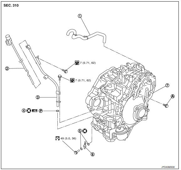
Exploded View
-
Air breather hose
-
CVT fluid level gauge
-
CVT fluid charging pipe
-
O-ring
-
Copper sealing washer
-
Fluid cooler tube
-
Transaxle assembly
A. Refer to INSTALLATION.
Removal and Installation
WARNING:
Do not remove the reservoir tank cap when the engine is hot. Serious burns could occur from highpressure engine coolant escaping from the reservoir tank. Wrap a thick cloth around the cap. Slowly turn a quarter turn to allow built-up pressure to escape. Carefully remove the cap by turning it all the way.
CAUTION:
-
Perform this step when the engine is cold.
-
When replacing TCM and transaxle assembly as a set, replace transaxle assembly first and then replace TCM. Refer to TM-8, "Description".
NOTE: When removing components such as hoses, tubes/lines, etc., cap or plug openings to prevent fluid from spilling.
REMOVAL
-
Remove the engine and transaxle assembly and front suspension member. Refer to EM-103, "Removal and Installation".
-
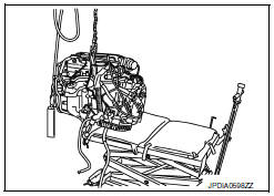
Lift with hoist and separate engine and transaxle assembly from front suspension member. Refer to EM- 103, "Removal and Installation".
-
Disconnect secondary speed sensor harness connector. Refer to TM-184, "Exploded View".
-
Disconnect CVT unit harness connector.
-
Remove CVT fluid charging pipe from transaxle assembly.
-
Disconnect starter harness connectors.
-
Remove starter assembly. Refer to STR-19, "Removal and Installation".
-
Remove upper rear CVT gusset bolt.
-
Remove transaxle assembly bolts with power tool.
-
Remove transaxle assembly from engine assembly with a hoist.
-
Remove air breather hose. Refer to TM-187, "Exploded View".
-
Remove CVT fluid cooler tube from transaxle assembly.
CAUTION: Do not reuse copper sealing washers.
INSTALLATION
Installation is in the reverse order of removal.
-
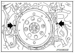
CAUTION: Check alignment of dowel pins when installing transaxle assembly to engine assembly.
-
 : Dowel pins
-
-
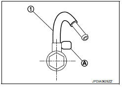
When installing CVT fluid cooler tube (1) to transaxle assembly:
-
Contact CVT fluid cooler tube a boss portion (A) of the transaxle case.
-
Tighten the bolt of CVT fluid cooler tube without moving the CVT fluid cooler tube.
CAUTION: Do not reuse copper sealing washers.
-
Align the torque converter stud bolts (B) and drive plate holes.
-
When using a suitable tool (A), set it to the alignment stud bolt which is used to align the torque converter to the drive plate.
-
Rotate torque converter so that the alignment stud bolt aligns with the position of the service hole
-
-
Rotate crankshaft so that the hole (A) for inserting alignment stud bolt of drive plate aligns with the service hole (B).
-
When not using suitable tool for alignment, insert stud bolt of torque converter into the hole (C) of drive plate, aligning the drive plate hole position and torque converter stud bolts.
CAUTION: Be careful not to strike the drive plate when installing the torque converter stud bolt.
-
-
When installing the torque converter nuts temporarily tighten the nuts. Then, after installing the engine and transaxle assembly bolts tighten the nuts to the specified torque.
-
 : Torque converter
nuts
: Torque converter
nuts
-
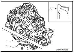
- When installing transaxle assembly to the engine assembly, install the bolts in accordance with the following.
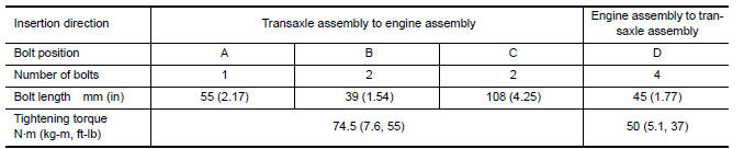
CAUTION:
-
When turning crankshaft, turn it clockwise as viewed from the front of the engine.
-
When tightening the nuts for the torque converter after installing the crankshaft pulley bolts, confirm the tightening torque of the crankshaft pulley bolts. Refer to EM-54, "Removal and Installation".
-
Rotate crankshaft several turns and check that transaxle rotates freely without binding after converter is installed to drive plate.
Inspection and Adjustment
INSPECTION BEFORE INSTALLATION
After inserting a torque converter to transaxle assembly, check that dimension (A) is within the reference value limit.
B : Scale
C : Straightedge
INSPECTION AFTER INSTALLATION
Check the following.
-
Check for CVT fluid leakage and check CVT fluid level. Refer to TM-155, "Inspection".
-
Check CVT position. Refer to TM-171, "Inspection and Adjustment".
-
Start and warm up the engine. Visually check that there is no leakage of engine coolant and CVT fluid.
ADJUSTMENT AFTER INSTALLATION
Erase TCM data.
-
Erase CVT fluid degradation level data. Refer to TM-38, "CONSULT Function".
-
When replacing the transaxle assembly, erase EEP ROM in TCM. Refer to TM-10, "Description".
 Air breather hose
Exploded View
Air cleaner case
Air breather hose
Transaxle assembly
Heater pipe
Clip
A. Paint mark
: Front
Removal an ...
 Unit disassembly and assembly
TORQUE CONVERTER
Exploded View
Torque converter
Transaxle assembly
Disassembly
Remove transaxle assembly. Refer to TM-188,
"Exploded View".
...
Other materials:
Both side front fog lamps are not turned on
Description
The front fog lamps do not turn ON in any setting.
Diagnosis Procedure
1.COMBINATION SWITCH (LIGHTING AND TURN SIGNAL SWITCH) INSPECTION
Check the combination switch (lighting and turn signal switch).
2.CHECK FRONT FOG LAMP REQUEST SIGNAL INPUT
CONSULT DATA MONITOR
Select "FR F ...
Power window and door lock/unlock switch RH
Reference Value
TERMINAL LAYOUT
PHYSICAL VALUES
POWER WINDOW AND DOOR LOCK/UNLOCK SWITCH RH
Fail Safe
FAIL-SAFE CONTROL
Switches to fail-safe control when malfunction is detected in encoder signal
that detects up/down speed and
direction of door glass. Switches to fail-safe con ...
Center speaker
Removal and Installation
REMOVAL
Remove the center speaker grille, using a suitable tool.
Remove the center speaker screws (A).
Pull out the center speaker (1), disconnect the harness connector
from the center speaker and remove.
INSTALLATION
Installation is in the reverse order ...
Nissan Maxima Owners Manual
- Illustrated table of contents
- Safety-Seats, seat belts and supplemental restraint system
- Instruments and controls
- Pre-driving checks and adjustments
- Monitor, climate, audio, phone and voice recognition systems
- Starting and driving
- In case of emergency
- Appearance and care
- Do-it-yourself
- Maintenance and schedules
- Technical and consumer information
Nissan Maxima Service and Repair Manual

0.0063