Nissan Maxima Service and Repair Manual: Front fog lamp circuit
Description
The IPDM E/R (intelligent power distribution module engine room) controls the front fog lamp relay based on inputs from the BCM over the CAN communication lines. When the front fog lamp relay is energized, power flows from the front fog lamp relay in the IPDM E/R to the front fog lamps.
Component Function Check
1.CHECK FRONT FOG LAMP OPERATION
WITHOUT CONSULT
- Activate IPDM E/R auto active test. Refer to PCS-11, "Diagnosis Description".
- Check that the front fog lamp is turned ON.
CONSULT
- Select "EXTERNAL LAMPS" of IPDM E/R active test item.
- While operating the test item, check that the front fog lamp is turned ON.
FOG : Front fog lamp ON
OFF : Front fog lamp OFF
Diagnosis Procedure
1.CHECK FRONT FOG LAMP FUSE
- Turn the ignition switch OFF.
- Check that the following fuse is not open.

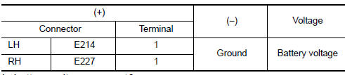
2.CHECK FRONT FOG LAMP OUTPUT VOLTAGE
CONSULT
- Turn the ignition switch OFF.
- Disconnect the front fog lamp connector.
- Turn the ignition switch ON.
- Select "EXTERNAL LAMPS" of IPDM E/R active test item.
- With EXTERNAL LAMPS ON, check the voltage between the fog lamp connector and ground.
3.CHECK FRONT FOG LAMP OPEN CIRCUIT
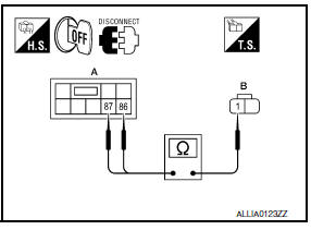
- Turn the ignition switch OFF.
- Disconnect IPDM E/R connector E200.
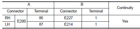
- Check continuity between the IPDM E/R harness connector (A) and the front fog lamp harness connector (B).
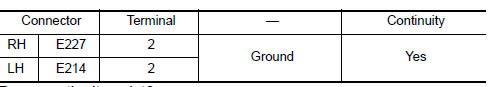
4.CHECK FRONT FOG LAMP GROUND CIRCUIT
Check continuity between the front fog lamp harness connector terminal and ground.
 Xenon headlamp
Description
OPERATION
Refer to EXL-10, "Component Description".
PRECAUTIONS FOR TROUBLE
DIAGNOSIS
Installation or removal of the connector must be done with the
lighting switch OFF.
When ...
 Parking lamp circuit
Description
The IPDM E/R (intelligent power distribution module engine room) controls the
tail lamp relay based on inputs from the BCM over the CAN communication
lines. When the tail lamp relay i ...
Other materials:
Remote keyless entry receiver
Removal and Installation
REMOVAL
Remove glove box assembly. Refer to IP-20, "Removal and
Installation".
Disconnect the harness connector from the remote keyless
entry receiver (1).
Remove the screw (a) and remote keyless entry receiver (1).
INSTALLATION
Installation ...
Sliding switch
Description
Sliding switch is equipped to the power seat switch LH on the seat frame. The
operation signal is input to the driver seat control unit when the sliding
switch is operated.
Component Function Check
1. CHECK FUNCTION
Select "SLIDE SW-FR", "SLIDE SW-RR" in "DATA MONITOR" mode wi ...
Headlamp
Description
Headlamp lighting when theft warning system is in alarm
phase.
Component Function Check
1.CHECK HEADLAMP OPERATION
Check if headlamps operate by lighting switch.
Diagnosis Procedure
1.CHECK HEADLAMP OPERATION
Refer to EXL-6, "Work Flow" (xenon type) or EXL-171,
"Work Flow" (ha ...
Nissan Maxima Owners Manual
- Illustrated table of contents
- Safety-Seats, seat belts and supplemental restraint system
- Instruments and controls
- Pre-driving checks and adjustments
- Monitor, climate, audio, phone and voice recognition systems
- Starting and driving
- In case of emergency
- Appearance and care
- Do-it-yourself
- Maintenance and schedules
- Technical and consumer information
Nissan Maxima Service and Repair Manual

0.0054