Nissan Maxima Service and Repair Manual: Reclining switch
Description
Reclining switch is equipped to the power seat switch LH on the seat frame. The operation signal is input to the driver seat control unit when the reclining switch is operated.
Component Function Check
1.CHECK FUNCTION
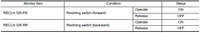
- Select "RECLN SW-FR", "RECLN SW-RR" in "DATA MONITOR" mode with CONSULT.
- Check reclining switch signal under the following conditions.
Diagnosis Procedure
Regarding Wiring Diagram information, refer to ADP-150, "Wiring Diagram".
1. CHECK RECLINING SWITCH SIGNAL
- Turn ignition switch OFF.
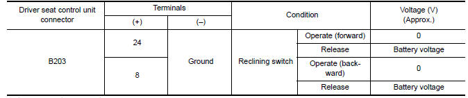
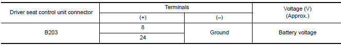
- Check voltage between driver seat control unit harness connector and ground.
2. CHECK RECLINING SWITCH CIRCUIT
- Turn ignition switch OFF.
- Disconnect driver seat control unit and power seat switch LH.
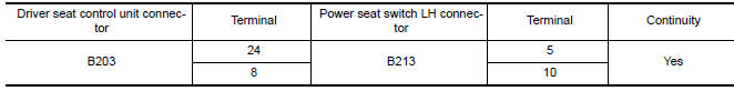
- Check continuity between driver seat control unit harness connector and power seat switch LH harness connector.
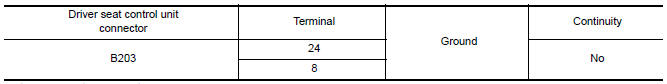
- Check continuity between driver seat control unit harness connector and ground.
3. CHECK DRIVER SEAT CONTROL UNIT OUTPUT
- Connect the driver seat control unit.
- Turn ignition switch ON.
- Check voltage between driver seat control unit harness connector and ground.
4. CHECK RECLINING SWITCH
Refer to ADP-51, "Component Inspection".
5. CHECK INTERMITTENT INCIDENT
Refer to GI-41, "Intermittent Incident".
Component Inspection
1. CHECK RECLINING SWITCH
- Turn ignition switch OFF.
- Disconnect power seat switch LH.
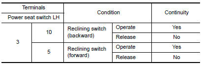
- Check continuity between power seat switch LH terminals.
 Sliding switch
Description
Sliding switch is equipped to the power seat switch LH on the seat frame. The
operation signal is input to the driver seat control unit when the sliding
switch is operated.
Component ...
 Lifting switch (front)
Description
Lifting switch (front) is equipped to the power seat switch LH on the seat
frame. The operation signal is input to the driver seat control unit when the
lifting switch (front) is oper ...
Other materials:
AMP on signal circuit
Description
When the audio system is turned on, a voltage signal is supplied from the AV
control unit to the BOSE speaker
amp. When this signal is received, the BOSE speaker amp. will turn on.
Diagnosis Procedure
1.CHECK AMP ON SIGNAL (BOSE SPEAKER AMP)
Turn audio system ON.
Check v ...
Towing recommended by NISSAN
CAUTION
Never tow CVT models with the front
wheels on the ground or 4 wheels on
the ground (forward or backward), as
this may cause serious and expensive
damage to the transmission. If it is necessary
to tow the vehicle with the rear
wheels raised always use towing dollies
under the ...
Parking, license plate and tail lamps system
Wiring Diagram
...
Nissan Maxima Owners Manual
- Illustrated table of contents
- Safety-Seats, seat belts and supplemental restraint system
- Instruments and controls
- Pre-driving checks and adjustments
- Monitor, climate, audio, phone and voice recognition systems
- Starting and driving
- In case of emergency
- Appearance and care
- Do-it-yourself
- Maintenance and schedules
- Technical and consumer information
Nissan Maxima Service and Repair Manual

0.0087