Nissan Maxima Service and Repair Manual: Sliding switch
Description
Sliding switch is equipped to the power seat switch LH on the seat frame. The operation signal is input to the driver seat control unit when the sliding switch is operated.
Component Function Check
1. CHECK FUNCTION
- Select "SLIDE SW-FR", "SLIDE SW-RR" in "DATA MONITOR" mode with CONSULT.
- Check sliding switch signal under the following conditions.
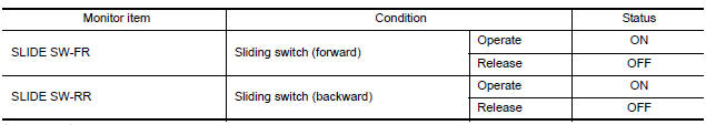
Is the indication normal?
Diagnosis Procedure
Regarding Wiring Diagram information, refer to ADP-150, "Wiring Diagram".
1. CHECK SLIDING SWITCH SIGNAL
- Turn ignition switch OFF.
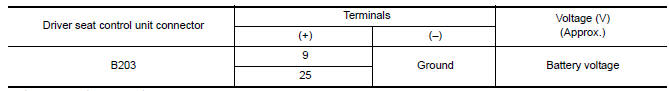
- Check voltage between driver seat control unit harness connector and ground.
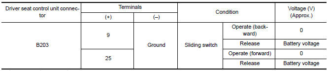
Is the inspection result normal?
2. CHECK SLIDING SWITCH CIRCUIT
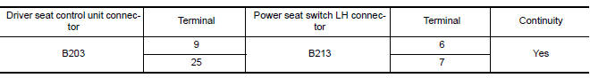
- Turn ignition switch OFF.
- Disconnect driver seat control unit and power seat switch LH.
- Check continuity between driver seat control unit harness connector and power seat switch LH harness connector.
- Check continuity between driver seat control unit harness connector and ground.
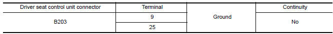
Is the inspection result normal?
3. CHECK DRIVER SEAT CONTROL UNIT OUTPUT
- Connect the driver seat control unit.
- Turn ignition switch ON.
- Check voltage between driver seat control unit harness connector and ground.
Is the inspection result normal?
4. CHECK SLIDING SWITCH
Pefer to ADP-51, "Component Inspection".
Is the inspection result normal?
5. CHECK INTERMITTENT INCIDENT
Refer to GI-41, "Intermittent Incident".
Is the inspection result normal?
Component Inspection
1. CHECK SLIDING SWITCH
- Turn ignition switch OFF.
- Disconnect power seat switch LH.
- Check continuity between power seat switch LH terminals.
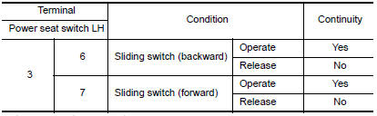
Is the inspection result normal?
 Power supply and ground circuit
BCM
BCM : Diagnosis Procedure
Regarding Wiring Diagram information, refer to BCS-67, "Wiring Diagram".
1. CHECK FUSE AND FUSIBLE LINK
Check if the following BCM fuses or fusible link are blown.
...
 Reclining switch
Description
Reclining switch is equipped to the power seat switch LH on the seat frame.
The operation signal is input to the driver seat control unit when the
reclining switch is operated.
Compo ...
Other materials:
Maintenance under severe operating conditions
Severe driving conditions
The maintenance intervals shown on the preceding pages are for normal
operating conditions. If the vehicle is mainly operated under severe driving
conditions as shown below, more frequent maintenance must be performed on the
following items as shown in the table.
...
Unit disassembly and assembly
FRONT COIL SPRING AND STRUT
Disassembly and Assembly
DISASSEMBLY
Install Tool (A) to the front coil spring and strut.
Tool number : ST35652000 ( - )
CAUTION: When installing Tool (A), wrap a
shop cloth around the front coil spring and strut to protect the parts from
damage.
Sec ...
Microphone signal circuit
Description
Voice signals are transmitted from the microphone to the Bluetooth control
unit using the microphone signal
circuits.
Diagnosis Procedure
1.CHECK HARNESS BETWEEN BLUETOOTH CONTROL UNIT AND MICROPHONE
Turn ignition switch OFF.
Disconnect Bluetooth control unit connector a ...
Nissan Maxima Owners Manual
- Illustrated table of contents
- Safety-Seats, seat belts and supplemental restraint system
- Instruments and controls
- Pre-driving checks and adjustments
- Monitor, climate, audio, phone and voice recognition systems
- Starting and driving
- In case of emergency
- Appearance and care
- Do-it-yourself
- Maintenance and schedules
- Technical and consumer information
Nissan Maxima Service and Repair Manual

0.0055