Nissan Maxima Service and Repair Manual: Power supply and ground circuit
BCM
BCM : Diagnosis Procedure
Regarding Wiring Diagram information, refer to BCS-67, "Wiring Diagram".
1. CHECK FUSE AND FUSIBLE LINK
Check if the following BCM fuses or fusible link are blown.
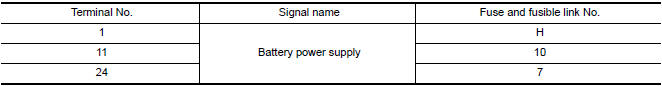
Is the fuse or fusible link blown?
2. CHECK POWER SUPPLY CIRCUIT
- Turn ignition switch OFF.
- Disconnect BCM.
- Check voltage between BCM harness connector and ground.
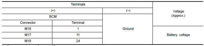
Is the measurement norma
3. CHECK GROUND CIRCUIT
Check continuity between BCM harness connector and ground.
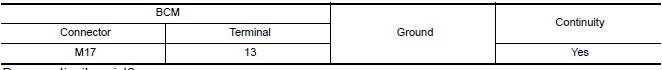
Does continuity exist?
DRIVER SEAT CONTROL UNIT
DRIVER SEAT CONTROL UNIT : Diagnosis Procedure
NOTE: Do not disconnect the battery negative terminal and the driver seat control unit connector until DTC is confirmed with CONSULT.
Regarding Wiring Diagram information, refer to ADP-150, "Wiring Diagram".
1. CHECK POWER SUPPLY CIRCUIT
- Turn ignition switch OFF.
- Disconnect driver seat control unit.
- Check voltage between driver seat control unit harness connector and ground.
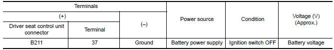
Is the inspection result normal?
2. CHECK GROUND CIRCUIT
Check continuity between the driver seat control unit harness connector and ground.

Is the inspection result normal?
DRIVER SEAT CONTROL UNIT : Special Repair Requirement
1.PERFORM ADDITIONAL SERVICE
Perform additional service when removing battery negative terminal.
AUTOMATIC DRIVE POSITIONER CONTROL UNIT
AUTOMATIC DRIVE POSITIONER CONTROL UNIT : Diagnosis Procedure
NOTE: Do not disconnect the battery negative terminal and the driver seat control unit connector until DTC is confirmed with CONSULT.
Regarding Wiring Diagram information, refer to ADP-150, "Wiring Diagram".
1. CHECK POWER SUPPLY CIRCUIT
- Turn ignition switch OFF.
- Disconnect automatic drive positioner control unit.
- Check voltage between automatic drive positioner control unit harness connector and ground.
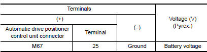
Is the inspection result normal?
2. CHECK GROUND CIRCUIT
Check continuity between the automatic drive positioner control unit harness connector and ground.
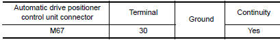
Is the inspection result normal?
AUTOMATIC DRIVE POSITIONER CONTROL UNIT : Special Repair Requirement
1.PERFORM ADDITIONAL SERVICE
Perform additional service when removing battery negative terminal.
 B2128 UART communication line
Description
Driver seat control unit performs UART communication with the automatic drive
positioner control unit using 1 communication line. Driver seat control unit
receives the operation signa ...
 Sliding switch
Description
Sliding switch is equipped to the power seat switch LH on the seat frame. The
operation signal is input to the driver seat control unit when the sliding
switch is operated.
Component ...
Other materials:
B2560 starter control relay
Description
Starter control relay, integrated in IPDM E/R, permits
the starter relay operation when in N or P position. It is
installed in parallel with the starter relay.
DTC Logic
DTC DETECTION LOGIC
NOTE:
If DTC B2560 is displayed with DTC
U1000, first perform the trouble diagno ...
Combination meter
Reference Value
VALUES ON THE DIAGNOSIS TOOL
NOTE:
* The monitor will indicate "OFF" even though
the brake warning lamp is on if either of the following conditions exist:
The parking brake is engaged
The brake fluid level is low
TERMINAL LAYOUT
PHYSICAL VALUES
...
Outside key antenna
Description
Detects whether Intelligent Key is outside the vehicle.
Integrated in front outside handle (driver side, passenger side) and installed
in rear bumper.
Component Function Check
NOTE:
The Signal Tech II Tool (J-50190) can be used to perform the following
functions. Refer to t ...
Nissan Maxima Owners Manual
- Illustrated table of contents
- Safety-Seats, seat belts and supplemental restraint system
- Instruments and controls
- Pre-driving checks and adjustments
- Monitor, climate, audio, phone and voice recognition systems
- Starting and driving
- In case of emergency
- Appearance and care
- Do-it-yourself
- Maintenance and schedules
- Technical and consumer information
Nissan Maxima Service and Repair Manual

0.0061