Nissan Maxima Service and Repair Manual: Can communication system
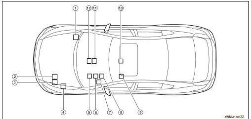
Component Parts Location
-
ABS actuator and electric unit (control unit) E26
-
TCM F15
-
ECM E10
-
4. IPDM E/R E17
-
BCM M19
-
Combination meter M24
-
Data link connector M22
-
Steering angle sensor M53
-
Driver seat control unit B203
-
Air bag diagnosis sensor unit M43
-
A/C auto amp. M37
-
AV control unit M156: With BOSE audio system - without navigation system M163: With BOSE audio system - with navigation system M119: With MID audio system

 Malfunction area chart
Main Line
Branch Line
Short Circuit
...
Other materials:
The ambient temperature display is incorrect
Description
The displayed ambient air temperature is higher
than the actual temperature.
The displayed ambient air temperature is lower
than the actual temperature.
Diagnosis Procedure
1.COMBINATION METER INPUT SIGNAL
Select "METER/M&A" on CON ...
U1243 display unit
Description
Part name
Description
DISPLAY UNIT
Display image is controlled by the serial communication from AV
control unit.
Inputs the RGB image signal (RGB, RGB area and RGB
synchronizing) from AV control unit and the auxiliary image ...
Satellite radio antenna
Removal and Installation
REMOVAL
Lower the headlining at the rear. Refer to INT-33, "Exploded
View".
Disconnect the harness connector (A) from satellite radio
antenna.
Remove the satellite radio antenna nut (B) and the satellite radio
antenna (1).
INSTALLATION
Ins ...
Nissan Maxima Owners Manual
- Illustrated table of contents
- Safety-Seats, seat belts and supplemental restraint system
- Instruments and controls
- Pre-driving checks and adjustments
- Monitor, climate, audio, phone and voice recognition systems
- Starting and driving
- In case of emergency
- Appearance and care
- Do-it-yourself
- Maintenance and schedules
- Technical and consumer information
Nissan Maxima Service and Repair Manual

0.005