Nissan Maxima Service and Repair Manual: Insufficient heating
Component Function Check
Symptom
- Insufficient heating
- No warm air comes out. (Airflow volume is normal.)
INSPECTION FLOW
1. CONFIRM SYMPTOM BY PERFORMING OPERATION CHECK - TEMPERATURE INCREASE
- Press the AUTO switch.
- Turn temperature control dial (driver side) clockwise until 32C (90F) is displayed.
- Check for hot air at discharge air outlets.
2. CHECK FOR ANY SYMPTOMS
Perform a complete operational check and check for any symptoms.
3. CHECK FOR SERVICE BULLETINS
Check for any service bulletins.
4. CHECK ENGINE COOLING SYSEM
- Check for proper engine coolant level. Refer to CO-10, "System Inspection".
- Check hoses for leaks or kinks.
- Check radiator cap. Refer to CO-10, "System Inspection".
- Check for air in cooling system.
5.CHECK SETTING OF TEMPERATURE SETTING TRIMMER
Using CONSULT, check the setting of "TEMP SET CORRECT" on "WORK SUPPORT" of HVAC.
- Check that the temperature setting trimmer is set to "− direction". NOTE: The control temperature can be set by the temperature setting trimmer.
- Set temperature control dial to "0".
6.CHECK WITH SELF-DIAGNOSIS FUNCTION OF CONSULT
- Using CONSULT, perform "SELF-DIAGNOSIS RESULTS" of HVAC.
- Check if any DTC No. is displayed in the trouble diagnosis results.
NOTE: If DTC is displayed along with DTC U1000 or U1010, first diagnose the DTC U1000 or U1010.
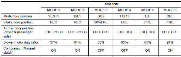
7.CHECK WITH ACTIVE TEST OF CONSULT
- Using CONSULT, perform "HVAC TEST" in "ACTIVE TEST" of HVAC to check each output device. Refer to HAC-26, "CONSULT Function". NOTE: Perform the ACTIVE TEST after starting the engine because the compressor is operating.
- Refer to the table and check the outlet, inlet, airflow temperature, blower motor control signal, magnet clutch operation, and air mix ratio. Visually check each operating condition, by listening for noise, touching air outlets with a hand, etc.
8. CHECK AIR DUCTS
Check for disconnected or leaking air ducts.
9. CHECK HEATER HOSE TEMPERATURES
- Start engine and warm it up to normal operating temperature.
- Touch both the inlet and outlet heater hoses. The inlet hose should be hot and the outlet hose should be warm.
10. CHECK ENGINE COOLANT SYSTEM
Check thermostat operation.
11. CHECK HEATER HOSES
Check heater hoses for proper installation.
12. CHECK HEATER HOSE TEMPERATURES
- Start engine and warm up to normal operating temperature.
- Touch both the inlet and outlet heater hoses. The inlet hose should be hot and the outlet hose should be warm.
 Insufficient cooling
Component Function Check
Symptom
Insufficient cooling
No cool air comes out. (Airflow volume is normal.)
INSPECTION FLOW
1. CONFIRM SYMPTOM BY PERFORMING OPERATION CHECK - TEMPERATURE DECRE ...
 Noise
Noise
Component Function Check
Symptom
Noise
Noise is heard when the A/C system operates.
INSPECTION FLOW
...
Other materials:
Center speaker
Removal and Installation
REMOVAL
Remove the center speaker grille, using a suitable tool.
Remove the center speaker screws (A).
Pull out the center speaker (1), disconnect the harness connector
from the center speaker and remove.
INSTALLATION
Installation is in the reverse order ...
Air fresheners
Most air fresheners use a solvent that could affect
the vehicle interior. If you use an air freshener,
take the following precautions:
Hanging-type air fresheners can cause permanent
discoloration when they contact vehicle
interior surfaces. Place the air freshener
in a location that all ...
Rear view monitor system
System Diagram
System Description
When the shift selector is in the R position, the display unit shows a view
to the rear of the vehicle. Lines which
indicate the vehicle clearance and distances are also displayed.
Component Parts Location
Tweeter LH M51
Center speaker M130
...
Nissan Maxima Owners Manual
- Illustrated table of contents
- Safety-Seats, seat belts and supplemental restraint system
- Instruments and controls
- Pre-driving checks and adjustments
- Monitor, climate, audio, phone and voice recognition systems
- Starting and driving
- In case of emergency
- Appearance and care
- Do-it-yourself
- Maintenance and schedules
- Technical and consumer information
Nissan Maxima Service and Repair Manual

0.0074