Nissan Maxima Service and Repair Manual: Wiring diagram
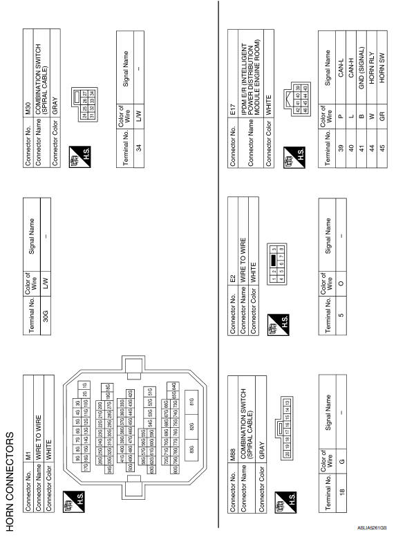
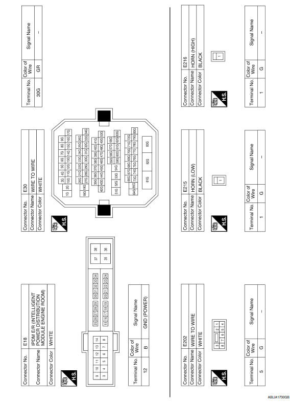
HORN
Wiring Diagram
 Precaution
Precaution for Supplemental Restraint System (SRS) "AIR BAG" and
"SEAT BELTPRE-TENSIONER"
The Supplemental Restraint System such as “AIR BAG” and “SEAT BELT
PRE-TENSIONER”, used alongwith ...
 Removal and installation
HORN
Removal and Installation
REMOVAL
Remove the engine under cover. Refer to EXT-16, "Removal and
Installation".
Position aside the front fender protector (LH). Refer to EXT-24,
"Remova ...
Other materials:
Loading tips
The GVW must not exceed GVWR
or GAWR as specified on the
F.M.V.S.S./C.M.V.S.S. certification
label.
Do not load the front and rear axle to
the GAWR. Doing so will exceed the
GVWR.
WARNING
Properly secure all cargo with
ropes or straps to help prevent it
from sliding or shif ...
License lamp finisher
Exploded View
License lamp finisher
Trunk request switch connector
Grommet Clip
Removal and Installat
REMOVAL
Remove the trunk lid finisher. Refer to INT-36, "Removal and
Installation".
Disconnect the harness connector (1) from the trunk request
switch.
Remove the ...
Oil pressure switch signal circuit
Description
Detects the engine oil pressure and transmits the oil
pressure switch signal to the IPDM E/R.
Component Function Check
1.COMBINATION METER INPUT SIGNAL
Select "METER/M&A" on CONSULT.
Monitor "OIL W/L" of "DATA MONITOR" while
operating ignition switc ...
Nissan Maxima Owners Manual
- Illustrated table of contents
- Safety-Seats, seat belts and supplemental restraint system
- Instruments and controls
- Pre-driving checks and adjustments
- Monitor, climate, audio, phone and voice recognition systems
- Starting and driving
- In case of emergency
- Appearance and care
- Do-it-yourself
- Maintenance and schedules
- Technical and consumer information
Nissan Maxima Service and Repair Manual

0.0054