Nissan Maxima Service and Repair Manual: Removal and installation
HORN
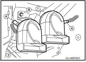
Removal and Installation
REMOVAL
- Remove the engine under cover. Refer to EXT-16, "Removal and Installation".
- Position aside the front fender protector (LH). Refer to EXT-24, "Removal and Installation".
- Disconnect the harness connectors (A) from the horns.
- Remove the horn bracket bolt (B).
- Remove horns (1 and 2).
INSTALLATION
Installation is in the reverse order of removal.
 Wiring diagram
HORN
Wiring Diagram
...
 Power outlet
...
Other materials:
Combination switch reading system
System Diagram
System Description
OUTLINE
BCM reads the status of the combination switch (light, turn
signal, wiper and washer) and recognizes the status of each switch.
BCM has a combination of 5 output terminals (OUTPUT 1 - 5) and 5
input terminals (INPUT 1 - 5) and reads a maximum ...
P0451 evap control system pressure sensor
Description
The EVAP control system pressure sensor detects pressure in the
purge line. The sensor output voltage to the ECM increases as pressure
increases
DTC Logic
DTC DETECTION LOGIC
DTC CONFIRMATION PROCEDURE
NOTE:
Never remove fuel filler cap during DTC confirmation procedur ...
Aux image signal circuit
Description
Transmits the image signal of AUX device from auxiliary input jacks to
AV control unit.
AV control unit transmits the image signal that is input to the
display unit.
Diagnosis Procedure
1.CHECK CONTINUITY AUX IMAGE SIGNAL CIRCUIT
Turn ignition switch OFF.
Disconnect ...
Nissan Maxima Owners Manual
- Illustrated table of contents
- Safety-Seats, seat belts and supplemental restraint system
- Instruments and controls
- Pre-driving checks and adjustments
- Monitor, climate, audio, phone and voice recognition systems
- Starting and driving
- In case of emergency
- Appearance and care
- Do-it-yourself
- Maintenance and schedules
- Technical and consumer information
Nissan Maxima Service and Repair Manual

0.0057