Nissan Maxima Owners Manual: Jacking up vehicle and removing the damaged tire
WARNING
- Never get under the vehicle while it is supported only by the jack. If it is necessary to work under the vehicle, support it with safety stands.
- Use only the jack provided with your vehicle to lift the vehicle. Do not use the jack provided with your vehicle on other vehicles. The jack is designed for lifting only your vehicle during a tire change.
- Use the correct jack-up points. Never use any other part of the vehicle for jack support.
- Never jack up the vehicle more than necessary.
- Never use blocks on or under the jack.
- Do not start or run the engine while vehicle is on the jack. It may cause the vehicle to move. This is especially true for vehicles with limited slip differentials.
- Do not allow passengers to stay in the vehicle while it is on the jack.
- Never run the engine with a wheel(s) off the ground. It may cause the vehicle to move.
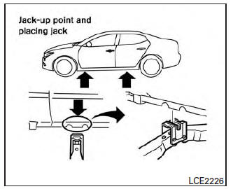
Always refer to the proper illustrations for the correct placement and jack-up points for your specific vehicle model and jack type.
Carefully read the caution label attached to the jack body and the following instructions.
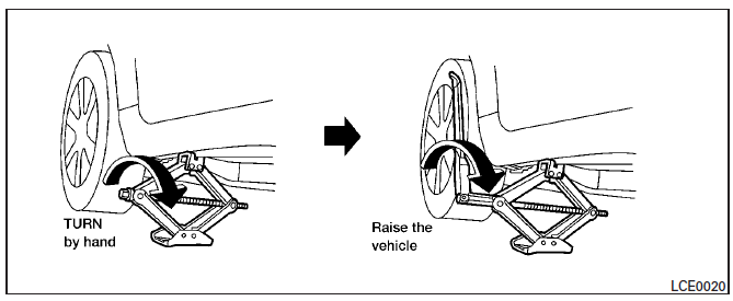
1. Loosen each wheel nut one or two turns by turning counterclockwise with the wheel nut wrench. Do not remove the wheel nuts until the tire is off the ground.
2. Place the jack directly under the jack-up point as illustrated so the top of the jack contacts the vehicle at the jack-up point.
Align the jack head between the two notches in the front or the rear as shown.
Also fit the groove of the jack head between the notches as shown.
The jack should be used on firm and level ground.
3. To lift the vehicle, securely hold the jack lever and rod with both hands. Carefully raise the vehicle until the tire clears the ground. Remove the wheel nuts and then remove the tire.
 Blocking wheels
A. Blocks
B. Flat tire
Place suitable blocks at both the front and back
of the wheel diagonally opposite the flat tire to
prevent the vehicle from moving when it is jacked
up.
WARNING
Be su ...
 Installing the spare tire
The spare tire is designed for emergency
use. For additional information, refer to
"Wheels and tires" in the "Do-it-yourself"
section of this manual.
1. Clean any mud or dirt from the surface ...
Other materials:
Front fog lamp
Exploded View
Front bumper fascia
Front fog lamp
Front fog lamp bracket
Clip
Spring nuts
Removal and Installation
FRONT FOG LAMP
Removal
Remove the front bumper fascia. Refer to EXT-16, "Removal and
Installation".
Disconnect the harness connector from the fog lamp.
R ...
ADP branch line circuit
Diagnosis Procedure
1.CHECK CONNECTOR
Turn the ignition switch OFF.
Disconnect the battery cable from the negative terminal.
Check the following terminals and connectors for damage, bend and
loose connection (unit side and connector
side).
Driver seat control unit
Harness connec ...
Parking brake switch
Description
The parking brake switch converts the status of the parking brake pedal to an
electric signal and transmits it to
the combination meter. The combination meter, through CAN communication,
transmits the signal to the ABS
actuator and electric unit (control unit).
Component Functi ...
Nissan Maxima Owners Manual
- Illustrated table of contents
- Safety-Seats, seat belts and supplemental restraint system
- Instruments and controls
- Pre-driving checks and adjustments
- Monitor, climate, audio, phone and voice recognition systems
- Starting and driving
- In case of emergency
- Appearance and care
- Do-it-yourself
- Maintenance and schedules
- Technical and consumer information
Nissan Maxima Service and Repair Manual

0.0116