Nissan Maxima Service and Repair Manual: Precaution
PRECAUTIONS
Precaution for Supplemental Restraint System (SRS) "AIR BAG" and "SEAT BELT PRE-TENSIONER"
The Supplemental Restraint System such as "AIR BAG" and "SEAT BELT PRE-TENSIONER", used along with a front seat belt, helps to reduce the risk or severity of injury to the driver and front passenger for certain types of collision. This system includes seat belt switch inputs and dual stage front air bag modules. The SRS system uses the seat belt switches to determine the front air bag deployment, and may only deploy one front air bag, depending on the severity of a collision and whether the front occupants are belted or unbelted.
Information necessary to service the system safely is included in the SR and SB section of this Service Manual.
WARNING:
-
To avoid rendering the SRS inoperative, which could increase the risk of personal injury or death in the event of a collision which would result in air bag inflation, all maintenance must be performed by an authorized NISSAN/INFINITI dealer.
-
Improper maintenance, including incorrect removal and installation of the SRS, can lead to personal injury caused by unintentional activation of the system. For removal of Spiral Cable and Air Bag Module, see the SR section.
-
Do not use electrical test equipment on any circuit related to the SRS unless instructed to in this Service Manual. SRS wiring harnesses can be identified by yellow and/or orange harnesses or harness connectors.
PRECAUTIONS WHEN USING POWER TOOLS (AIR OR ELECTRIC) AND HAMMERS
WARNING:
-
When working near the Airbag Diagnosis Sensor Unit or other Airbag System sensors with the Ignition ON or engine running, DO NOT use air or electric power tools or strike near the sensor(s) with a hammer. Heavy vibration could activate the sensor(s) and deploy the air bag(s), possibly causing serious injury.
-
When using air or electric power tools or hammers, always switch the Ignition OFF, disconnect the battery and wait at least 3 minutes before performing any service.
Precaution for Procedure without Cowl Top Cover
When performing the procedure after removing cowl top cover, cover the lower end of windshield with urethane, etc.
Precaution for Work
-
When removing or disassembling each component, be careful not to damage or deform it. If a component may be subject to interference, be sure to protect it with a shop cloth.
-
When removing (disengaging) components with a screwdriver or similar tool, be sure to wrap the component with a shop cloth or vinyl tape to protect it.
-
Protect the removed parts with a shop cloth and prevent them from being dropped.
-
Replace a deformed or damaged clip.
-
If a part is specified as a non-reusable part, always replace it with a new one.
-
Be sure to tighten bolts and nuts securely to the specified torque.
-
After installation is complete, be sure to check that each part works properly.
-
Follow the steps below to clean components:
-
Water soluble dirt:
-
-
Dip a soft cloth into lukewarm water, wring the water out of the cloth and wipe the dirty area.
-
Then rub with a soft, dry cloth.
-
Oily dirt:
-
Dip a soft cloth into lukewarm water with mild detergent (concentration: within 2 to 3%) and wipe the dirty area.
-
Then dip a cloth into fresh water, wring the water out of the cloth and wipe the detergent off.
-
Then rub with a soft, dry cloth.
-
-
Do not use organic solvent such as thinner, benzene, alcohol or gasoline.
-
For genuine leather seats, use a genuine leather seat cleaner.
-
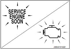
Precaution for On Board Diagnosis (OBD) System of CVT and Engine
The ECM has an on board diagnostic system. It will light up the malfunction indicator (MIL) to warn the driver of a malfunction causing emission deterioration.
CAUTION:
-
Be sure to turn the ignition switch OFF and disconnect the battery cable from the negative terminal before any repair or inspection work. The open/short circuit of related switches, sensors, solenoid valves, etc. will cause the MIL to light up.
-
Be sure to connect and lock the connectors securely after work. A loose (unlocked) connector will cause the MIL to light up due to an open circuit. (Be sure the connector is free from water, grease, dirt, bent terminals, etc.)
-
Be sure to route and secure the harnesses properly after work. Interference of the harness with a bracket, etc. may cause the MIL to light up due to a short circuit.
-
Be sure to connect rubber tubes properly after work. A misconnected or disconnected rubber tube may cause the MIL to light up due to a malfunction of the EVAP system or fuel injection system, etc.
-
Be sure to erase the unnecessary malfunction information (repairs completed) from the TCM and ECM before returning the vehicle to the customer.
Precaution for TCM or Transaxle Assembly Replacement
CAUTION:
-
To replace TCM, refer to TM-8, "Description".
-
To replace transaxle assembly, refer to TM-10, "Description".
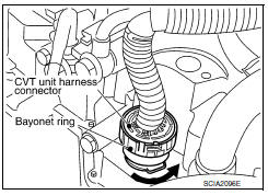
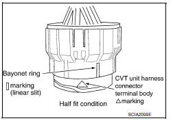
Removal and Installation Procedure for CVT Unit Connector
REMOVAL
Rotate bayonet ring counterclockwise. Pull out CVT unit harness connector upward and remove it.
INSTALLATION
-
Align
 marking on
CVT unit harness connector terminal body
with
marking on
CVT unit harness connector terminal body
with  marking on bayonet ring. Insert CVT unit
harness connector.
marking on bayonet ring. Insert CVT unit
harness connector.Then rotate bayonet ring clockwise.
2. Rotate bayonet ring clockwise until Δ marking on CVT unit harness connector terminal body is aligned with the slit on bayonet ring as shown in the figure (correctly fitting condition). Install CVT unit harness connector to CVT unit harness connector terminal body.
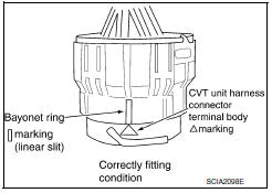
CAUTION:
-
Securely align Δ marking on CVT unit harness connector terminal body with bayonet ring slit. Then, be careful not to make a half fit condition as shown in the figure.
-
Never mistake the slit of bayonet ring for other dent portion.
Precaution
- Turn ignition switch OFF and disconnect negative battery cable before connecting or disconnecting the TCM harness connector. Because battery voltage is applied to TCM even if ignition switch is turned OFF.
- When connecting or disconnecting pin connectors into or from TCM, do not damage pin terminals (bend or break).
Check that there are not any bends or breaks on TCM pin terminal, when connecting pin connectors.
- Perform TCM input/output signal inspection and check whether TCM functions normally or not before replacing TCM.
TM-119, "Reference Value".
-
Perform "DTC Confirmation Procedure" after performing each TROUBLE DIAGNOSIS.
If the repair is completed the DTC should not be displayed in the "DTC Confirmation Procedure".
-
Always use the specified brand of CVT fluid. Refer to MA-15, "FOR USA AND CANADA : Fluids and Lubricants" (For United States and Canada), MA-16, "FOR MEXICO : Fluids and Lubricants" (For Mexico).
-
Use lint-free paper, not cloth rags, during work.
-
Dispose of the waste oil using the methods prescribed by law, ordinance, etc. after replacing the CVT fluid.
Service Notice or Precaution
CVT FLUID COOLER SERVICE
If CVT fluid contains friction material (clutches, brakes, etc.), or if a CVT is replaced, inspect and clean the CVT fluid cooler mounted in the radiator or replace the radiator. Flush cooler lines using cleaning solvent and compressed air after repair. For CVT fluid cooler cleaning procedure, refer to TM-157, "Cleaning". For radiator replacement, refer to CO-14, "Removal and Installation".
OBD-II SELF-DIAGNOSIS
-
CVT self diagnosis is performed by the TCM in combination with the ECM. The results can be read through the blinking pattern of the Malfunction Indicator Lamp (MIL). Refer to the table on TM-38, "CONSULT Function" for the indicator used to display each self diagnostic results.
-
The self diagnostic results indicated by the MIL are automatically stored in both the ECM and TCM memories.
Always perform the procedure on TM-36, "Diagnosis Description" to complete the repair and avoid unnecessary blinking of the MIL.
For details of OBD-II, refer to EC-127, "Diagnosis Description".
-
Certain systems and components, especially those related to OBD, may use the new style slide-locking type harness connector. For description and how to disconnect, refer to PG-57.
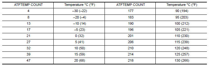
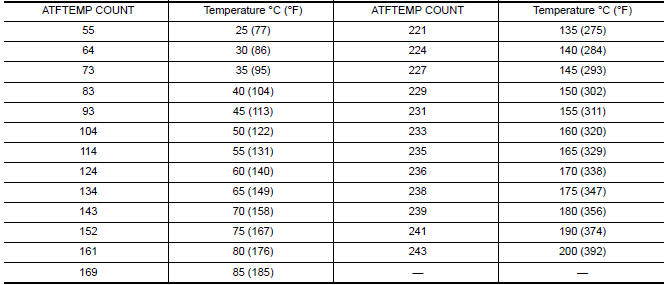
ATFTEMP COUNT Conversion Table
 Symptom diagnosis
SYSTEM SYMPTOM
Symptom Table
The diagnostics item numbers show the sequence for
inspection. Inspect in order from item 1.
...
 Preparation
PREPARATION
Special Service Tools
Commercial Service Tools
...
Other materials:
Service data and specifications (SDS)
Steering Wheel
Steering Angle
Steering Column
STEERING COLUMN LENGTH
STEERING COLUMN ROTATING TORQUE
TILT MECHANISM OPERATING RANGE
Steering Gear
STEERING OUTER SOCKET AND INNER SOCKET
RACK STROKE
RACK SLIDING FORCE
Oil Pump
Steering Fluid
...
Magnet clutch control system
System Diagram
System Description
The A/C auto amp. controls A/C compressor operation by ambient temperature,
intake air temperature and
signal from ECM.
SYSTEM OPERATION
When the A/C switch, the AUTO switch, or the DEF switch is pressed, or when
shifting mode position to D/F,
the A/C ...
Shift lock system
System Diagram
System Description
The selector lever cannot be shifted from "P" position to any other position
unless the ignition switch is in the
ON position and the brake pedal is depressed.
Component Parts Location
BCM (view with combination meter
removed)
Stop la ...
Nissan Maxima Owners Manual
- Illustrated table of contents
- Safety-Seats, seat belts and supplemental restraint system
- Instruments and controls
- Pre-driving checks and adjustments
- Monitor, climate, audio, phone and voice recognition systems
- Starting and driving
- In case of emergency
- Appearance and care
- Do-it-yourself
- Maintenance and schedules
- Technical and consumer information
Nissan Maxima Service and Repair Manual

0.0063