Nissan Maxima Service and Repair Manual: Preparation
PREPARATION
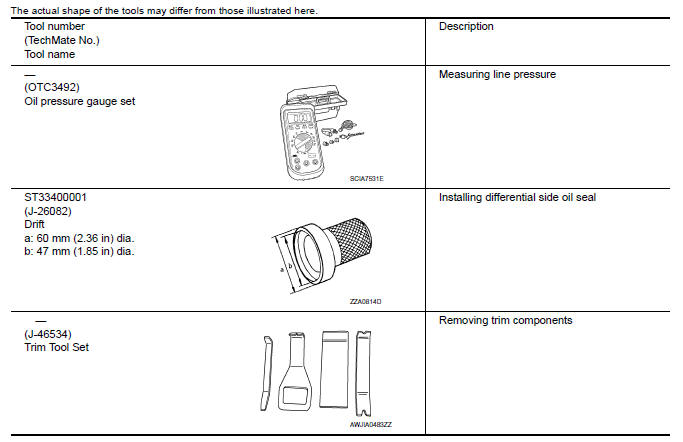
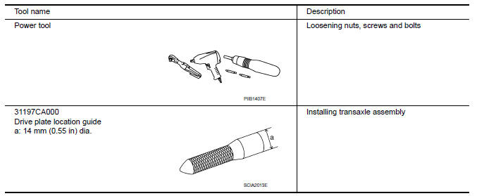
Special Service Tools
Commercial Service Tools
 Precaution
PRECAUTIONS
Precaution for Supplemental Restraint System (SRS) "AIR
BAG" and "SEAT BELT
PRE-TENSIONER"
The Supplemental Restraint System such as "AIR BAG" and
"SEAT BELT PRE-TENSIONER", used a ...

Other materials:
Diagnosis system (IPDM E/R)
Diagnosis Description
AUTO ACTIVE TEST
Description
In auto active test mode, the IPDM E/R sends a drive signal to the following
systems to check their operation.
Oil pressure warning lamp
Front wiper (LO, HI)
Parking lamps
Side marker lamps
License plate lamps
Tail lamps
Front f ...
Instrument Panel
Vent
Headlight/fog light/turn signal switch
Supplemental front-impact air bag. Horn
Meters and gauges. Warning and indicator lights. Vehicle information
display
Paddle shifters (if so equipped)
Wiper and washer switch
Audio controls*. Navigation controls*
Hazard warning ...
Ground
Ground Distribution
MAIN HARNESS
ENGINE ROOM HARNESS
FRONT END MODULE HARNESS
ENGINE CONTROL HARNESS
BODY HARNESS
BODY NO. 2 HARNESS
...
Nissan Maxima Owners Manual
- Illustrated table of contents
- Safety-Seats, seat belts and supplemental restraint system
- Instruments and controls
- Pre-driving checks and adjustments
- Monitor, climate, audio, phone and voice recognition systems
- Starting and driving
- In case of emergency
- Appearance and care
- Do-it-yourself
- Maintenance and schedules
- Technical and consumer information
Nissan Maxima Service and Repair Manual

0.0067