Nissan Maxima Service and Repair Manual: Rear door glass
Exploded View
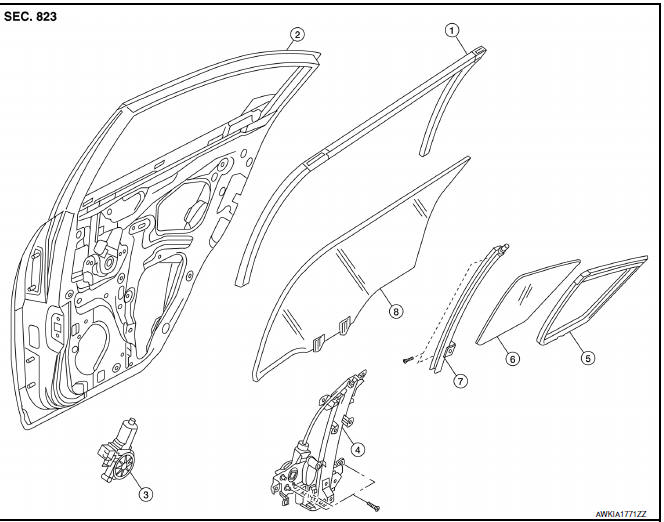
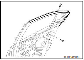
- Door glass run
- Door panel
- Window motor
- Regulator assembly
- Partition glass run
- Partition glass
- Partition sash
- Door glass
Removal and Installation
REMOVAL
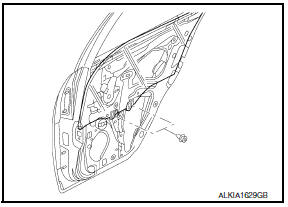
- Remove the rear door finisher. Refer to INT-21, "Removal and Installation".
- Position the vapor barrier aside.
- Temporarily reconnect the power window switch and raise/lower the door window until the glass bolts can be seen.
- Remove the glass bolts, and place the glass on the inner bottom of the panel.
- Remove the partition sash from the glass run.
- Remove the partition sash bolt (lower) and screw (upper) to remove the sash.
- Remove the partition glass and door glass from the inside of the panel.
INSTALLATION
Installation is in the reverse order of removal.
Inspection and Adjustment
FITTING INSPECTION
- Check that the glass is securely fit into the glass run groove.
- Lower the glass slightly [approximately 10 to 20 mm (0.39 to 0.79 in)], and check that the clearance to the sash is parallel. If the clearance between the glass and sash is not parallel, loosen the regulator bolts, guide rail bolts, and glass and carrier plate bolts to correct the glass position.
 Front regulator
Exploded View
Door panel
Door glass
Regulator assembly
Door module assembly
Window motor
Removal and Installation
REMOVAL
Remove the front door finisher. Refer to INT-18, "R ...
 Rear regulator
Rear Door Glass Regulator
REMOVAL
Remove the rear door finisher. Refer to INT-21, "Removal and
Installation".
Position aside the vapor barrier.
Temporarily reconnect the power window ...
Other materials:
Inspection and adjustment
ADDITIONAL SERVICE WHEN REMOVING BATTERY NEGATIVE TERMINAL
ADDITIONAL SERVICE WHEN REMOVING BATTERY NEGATIVE TERMINAL : Description
Initial setting is necessary when battery terminal is removed.
CAUTION:
The following specified operations are not performed under the
non-initialized condition. ...
ECU diagnosis information
BCM (BODY CONTROL MODULE)
Reference Value
NOTE:
The Signal Tech II Tool (J-50190) can be used to perform the following
functions. Refer to the Signal Tech II
User Guide for additional information.
Activate and display TPMS transmitter IDs
Display tire pressure reported by the TPMS tran ...
Precaution
Precaution for Supplemental Restraint System (SRS) "AIR BAG" and
"SEAT BELT PRE-TENSIONER"
The Supplemental Restraint System such as "AIR BAG" and "SEAT BELT
PRE-TENSIONER", used along with a front seat belt, helps to reduce the risk
or severity of injury to the driver and front passenger for ...
Nissan Maxima Owners Manual
- Illustrated table of contents
- Safety-Seats, seat belts and supplemental restraint system
- Instruments and controls
- Pre-driving checks and adjustments
- Monitor, climate, audio, phone and voice recognition systems
- Starting and driving
- In case of emergency
- Appearance and care
- Do-it-yourself
- Maintenance and schedules
- Technical and consumer information
Nissan Maxima Service and Repair Manual

0.0089