Nissan Maxima Service and Repair Manual: Front regulator
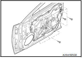
Exploded View
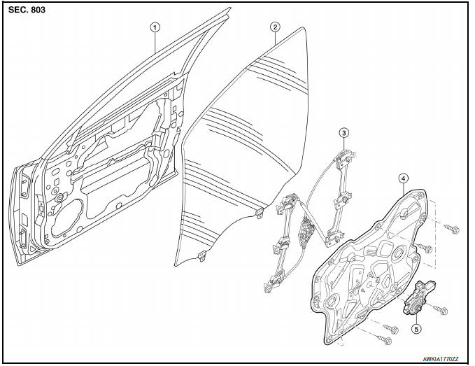
- Door panel
- Door glass
- Regulator assembly
- Door module assembly
- Window motor
Removal and Installation
REMOVAL
- Remove the front door finisher. Refer to INT-18, "Removal and Installation".
- Remove the adhesive bolt hole covers.
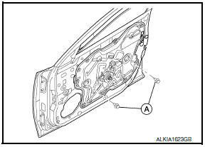
- Reconnect the window switch to raise/lower the door glass until the door glass bolts (A) can be seen.
- Remove the door glass bolts (A)
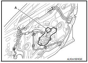
- Raise the door glass and hold with a suction lifter (A).
- Disconnect the harness connector (A) from the window motor.
- Remove the door module assembly mounting bolts.
- Remove the door module assembly.
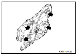
INSPECTION AFTER REMOVAL
Check the regulator assembly for the following items. If a malfunction is detected, replace or grease it.
- Wire wear
- Regulator deformation
- Grease condition for each sliding part
Apply multi-purpose grease at the locations shown.
INSTALLATION
Installation is in the reverse order of removal.
- Make sure the glass is securely set into the glass run groove.
- Lower the glass slightly [approx. 10 to 20 mm (0.39 to 0.79 in)] and make sure the clearance to the sash is parallel. If the clearance between the glass and sash is not parallel, loosen the regulator mounting bolts, guide rail mounting bolts, and glass and guide rail mounting bolts to adjust the glass position.
Inspection and Adjustment
SYSTEM INITIALIZATION
If any of the following work has been done, initialize the system. Refer to PWC-7, "ADDITIONAL SERVICE WHEN REMOVING BATTERY NEGATIVE TERMINAL : Special Repair Requirement".
- Electric power supply to power window switch or motor is interrupted by blown fuse or disconnecting battery cable, etc.
- Removal and installation of the regulator assembly.
- Removal and installation of the motor from the regulator assembly.
- Removal and installation of the harness connector of the power window switch.
- Operate the regulator assembly as a unit.
- Removal and installation of the door glass.
- Removal and installation of the door glass run.
- - Window is partly opened and/or closed many times without being fully closed.
Initialization
After installing each component to the vehicle, follow the steps below.
- Disconnect the negative battery terminal or disconnect the power window switch harness connector temporarily, then reconnect after at least 1 minute.
- Turn ignition switch ON.
- Open the window fully by operating the power window switch. (Exclude this procedure if the window is already fully opened.)
- Fully raise the power window switch in up direction (auto close position) and hold. Keep holding the switch even when window is completely closed and then release after 3 seconds have passed.
- Inspect the anti-pinch system function.
NOTE: Initialization may be cancelled with continuous opening and closing operation. In this case, initialize the system.
INSPECT THE FUNCTION OF THE ANTI-PINCH SYSTEM
To inspect the anti-pinch system
 Front door glass
Exploded View
Door panel
Door glass
Regulator assembly
Door module assembly
Window motor
Removal and Installation
REMOVAL
Remove the front door finisher. Refer to INT-18, "Rem ...
 Rear door glass
Exploded View
Door glass run
Door panel
Window motor
Regulator assembly
Partition glass run
Partition glass
Partition sash
Door glass
Removal and Installation
REMOVAL
...
Other materials:
Battery saver output/power supply circuit
Description
Provides the interior room lamp power supply. Also cuts the power supply when
the interior room lamp battery saver is activated.
Component Function Check
1.CHECK BATTERY SAVER OUTPUT/POWER SUPPLY FUNCTION
CONSULT
Turn ignition switch ON.
Turn each interior room lamp ON.
...
U1000 CAN comm circuit
Description
Refer to LAN-24, "CAN Communication Signal Chart".
DTC Logic
DTC DETECTION LOGIC
DTC
Trouble diagnosis name
DTC detecting condition
Possible cause
U1000
CAN COMM CIRCUIT
Driver seat control unit cannot communicate to other control
units.
...
Door outside molding
Exploded View
Front door sash molding
Front door outside molding
Rear door outside molding
Rear door sash molding (lower)
Rear door sash molding (upper)
Pawl
Removal and Installation
FRONT DOOR OUTSIDE MOLDING
Removal
Open the front door window fully.
Remove the ...
Nissan Maxima Owners Manual
- Illustrated table of contents
- Safety-Seats, seat belts and supplemental restraint system
- Instruments and controls
- Pre-driving checks and adjustments
- Monitor, climate, audio, phone and voice recognition systems
- Starting and driving
- In case of emergency
- Appearance and care
- Do-it-yourself
- Maintenance and schedules
- Technical and consumer information
Nissan Maxima Service and Repair Manual

0.0053