Nissan Maxima Service and Repair Manual: Front door glass
Exploded View
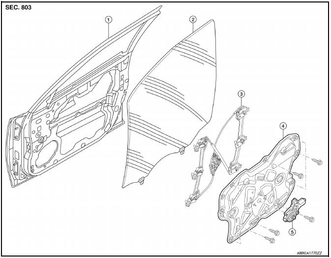
- Door panel
- Door glass
- Regulator assembly
- Door module assembly
- Window motor
Removal and Installation
REMOVAL
- Remove the front door finisher. Refer to INT-18, "Removal and Installation".
- Remove the adhesive bolt hole covers.
- Reconnect the window switch to raise/lower the door glass until the door glass bolts (A) can be seen.
- Remove the door glass bolts (A).
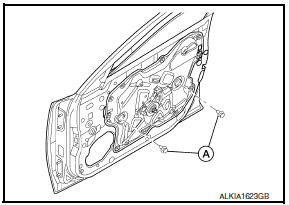
- While holding the door glass, raise it at the rear end to pull the door glass out of the sash toward the outside of the door.
Installation
Installation is in the reverse order of removal.
- Check that the door glass is securely set into the glass run groove.
- Lower the door glass slightly [approximately 10 to 20 mm (0.39 to 0.79 in)] and check that the clearance to the sash is parallel. If the clearance between the door glass and sash is not parallel, loosen the regulator bolts, guide rail bolts, and door glass and guide rail bolts to correct the glass position.
Inspection and Adjustment
SYSTEM INITIALIZATION
If any of the following work has been done, initialize the system. Refer to PWC-7, "ADDITIONAL SERVICE WHEN REMOVING BATTERY NEGATIVE TERMINAL : Special Repair Requirement".
- Electric power supply to power window switch or motor is interrupted by blown fuse or disconnecting battery cable, etc.
- Removal and installation of the regulator assembly.
- Removal and installation of the motor from the regulator assembly.
- Removal and installation of the harness connector of the power window switch.
- Operate the regulator assembly as a unit.
- Removal and installation of the door glass.
- Removal and installation of the door glass run.
- Window is partly opened and/or closed many times without being fully closed.
INSPECT THE FUNCTION OF THE ANTI-PINCH SYSTEM
To inspect the anti-pinch system, refer to PWC-7, "ADDITIONAL SERVICE WHEN REMOVING BATTERY NEGATIVE TERMINAL : Special Repair Requirement".
 Rear window glass
Exploded View
Rear window glass
Spacer
Rubber dam (if equipped)
Primer
Rear window molding
Adhesive
16 +2, -0 mm (0.63 +0.08, - 0 in)
7+ 2, - 0 mm (0.28 + 0.08, - ...
 Front regulator
Exploded View
Door panel
Door glass
Regulator assembly
Door module assembly
Window motor
Removal and Installation
REMOVAL
Remove the front door finisher. Refer to INT-18, "R ...
Other materials:
C1110, C1153, C1170 ABS actuator and electric unit (control unit)
DTC Logic
DTC DETECTION LOGIC
DTC CONFIRMATION PROCEDURE
1.CHECK SELF-DIAGNOSIS RESULTS
Check the self-diagnosis results.
Diagnosis Procedure
1.REPLACE ABS ACTUATOR AND ELECTRIC UNIT (CONTROL UNIT)
CAUTION:
Replace ABS actuator and electric unit (control unit) when self-diagnostic
...
P1078, P1084 EVT control position sensor
Description
Exhaust valve timing control position sensor detects the concave
groove of the exhaust camshaft rear end.
This sensor signal is used for sensing a position of the exhaust camshaft.
This sensor uses a Hall IC.
Based on the position of the exhaust camshaft, ECM controls
e ...
Parking, license plate and tail lamps are not turned on
Description
The parking, license plate and tail lamps do not turn ON in with any lighting
switch setting.
Diagnosis Procedure
1.COMBINATION SWITCH (LIGHTING AND TURN SIGNAL SWITCH) INSPECTION
Check the combination switch (lighting and turn signal switch).
2.CHECK TAIL LAMP RELAY REQUEST SIGNA ...
Nissan Maxima Owners Manual
- Illustrated table of contents
- Safety-Seats, seat belts and supplemental restraint system
- Instruments and controls
- Pre-driving checks and adjustments
- Monitor, climate, audio, phone and voice recognition systems
- Starting and driving
- In case of emergency
- Appearance and care
- Do-it-yourself
- Maintenance and schedules
- Technical and consumer information
Nissan Maxima Service and Repair Manual

0.0082