Nissan Maxima Owners Manual: Installing the spare tire
The spare tire is designed for emergency use. For additional information, refer to "Wheels and tires" in the "Do-it-yourself" section of this manual.
1. Clean any mud or dirt from the surface between the wheel and hub.
2. Carefully put the spare tire on and tighten the wheel nuts finger tight.
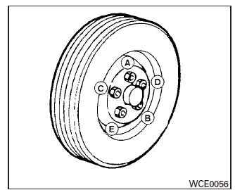
3. With the wheel nut wrench, tighten wheel nuts alternately and evenly in the sequence illustrated ( A , B , C , D , E ) until they are tight.
4. Lower the vehicle slowly until the tire touches the ground. Then, with the wheel nut wrench, tighten the wheel nuts securely in the sequence illustrated ( A , B , C , D , E ). Lower the vehicle completely.
WARNING
- Incorrect wheel nuts or improperly
tightened wheel nuts can cause the
wheel to become loose or come off.
This could cause an accident.
- Do not use oil or grease on the wheel studs or nuts. This could cause the nuts to become loose.
- Retighten the wheel nuts when the vehicle has been driven for 600 miles (1,000 km) (also in cases of a flat tire, etc.).
As soon as possible, tighten the wheel nuts to the specified torque with a torque wrench.
Wheel nut tightening torque: 83 ft-lb (112 N*m)
The wheel nuts must be kept tightened to specification at all times. It is recommended that wheel nuts be tightened to specifications at each lubrication interval.
Adjust tire pressure to the COLD pressure.
COLD pressure: After vehicle has been parked for 3 hours or more or driven less than 1 mile (1.6 km).
COLD tire pressures are shown on the Tire and Loading Information label affixed to the driver's door opening.
5. Securely store the flat tire and jacking equipment in the vehicle.
6. Place the spare tire cover and the trunk floor carpeting over the damaged tire.
7. Close the trunk.
WARNING
- Always make sure that the spare tire and jacking equipment are properly secured after use. Such items can become dangerous projectiles in an accident or sudden stop.
- The spare tire is designed for emergency use. Refer to specific instruction under the heading "Wheels and tires" in the "Do-it-yourself" section of this manual.
 Jacking up vehicle and removing the damaged tire
WARNING
Never get under the vehicle while it is
supported only by the jack. If it is necessary
to work under the vehicle, support
it with safety stands.
Use only the jack provided with ...
 Jump starting
To start your engine with a booster battery, the
instructions and precautions below must be followed.
WARNING
If done incorrectly, jump starting can
lead to a battery explosion, resulting in
...
Other materials:
Diagnosis system (BCM)
COMMON ITEM
COMMON ITEM : CONSULT Function (BCM - COMMON ITEM)
APPLICATION ITEM
CONSULT performs the following functions via CAN
communication with BCM.
SYSTEM APPLICATION
BCM can perform the following functions.
INTELLIGENT KEY
INTELLIGENT KEY : CONSULT Function (BCM - INTELLIGENT
...
Active engine brake
The Active Engine Brake function adds subtle
deceleration by controlling CVT gear ratio, depending
on the cornering condition calculated
from driver's steering input and plural sensors.
This benefit is for easier traceability and less
workload of adjusting speed with braking at corners.
Th ...
Child safety rear door lock
Child safety locks help prevent the rear doors
from being opened accidentally, especially when
small children are in the vehicle.
The child safety lock levers are located on the
edge of the rear doors.
When the lever is in the unlock position 2 , the
door can be opened from the outside ...
Nissan Maxima Owners Manual
- Illustrated table of contents
- Safety-Seats, seat belts and supplemental restraint system
- Instruments and controls
- Pre-driving checks and adjustments
- Monitor, climate, audio, phone and voice recognition systems
- Starting and driving
- In case of emergency
- Appearance and care
- Do-it-yourself
- Maintenance and schedules
- Technical and consumer information
Nissan Maxima Service and Repair Manual

0.0061