Nissan Maxima Service and Repair Manual: Front wiper does not operate
Description
The front wiper does not operate under any operation conditions
Diagnosis Procedure
1. CHECK WIPER RELAY OPERATION
IPDM E/R AUTO ACTIVE TEST
- Start IPDM E/R auto active test. Refer to PCS-11, "Diagnosis Description".
- Check that the front wiper operates at the LO/HI operation.
CONSULT ACTIVE TEST
- Select "FRONT WIPER" of IPDM E/R active test item.
- While operating the test item, check front wiper LO/HI operation and OFF.
LO : Front wiper LO operation<>
HI : Front wiper HI operation<>
OFF :
Stop the front wiper.
2. CHECK FRONT WIPER MOTOR FUSE
- Turn the ignition switch OFF.
- Check that the front wiper motor fuse 30A (No. 55, located in the IPDM E/R) is not blown
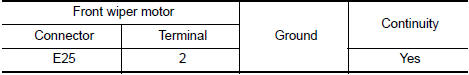
3. CHECK FRONT WIPER MOTOR (GND) OPEN CIRCUIT
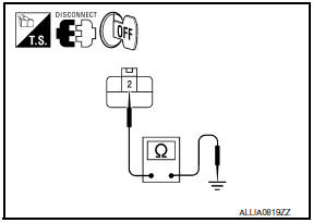
- Turn the ignition switch OFF.
- Disconnect front wiper motor.
- Check continuity between front wiper motor harness connector
and ground.
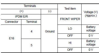
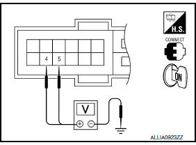
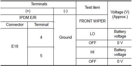
4. CHECK FRONT WIPER MOTOR OUTPUT VOLTAGE
CONSULT ACTIVE TEST
- Turn the ignition switch OFF.
- Disconnect front wiper motor.
- Turn the ignition switch ON.
- Select "FRONT WIPER" of IPDM E/R active test item.
- While operating the test item, check voltage between IPDM E/R
harness connector and ground.
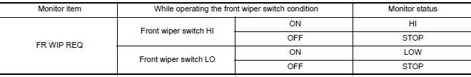
5. CHECK FRONT WIPER REQUEST SIGNAL INPUT
CONSULT DATA MONITOR
- Select "FR WIP REQ" of IPDM E/R "DATA MONITOR" item.
- Switch the front wiper switch to HI and LO.
- While operating the front wiper switch, check the monitor status.
6. CHECK COMBINATION SWITCH (WIPER AND WASHER SWITCH)
Perform the inspection of the combination switch (wiper and washer switch).
 Front wiper and washer system symptoms
Symptom Table
CAUTION:Perform the self-diagnosis with CONSULT
before performing the diagnosis by symptom. Perform thediagnosis by DTC if
DTC is detected.
...
 Normal operating condition
Description
FRONT WIPER MOTOR PROTECTION FUNCTION
IPDM E/R may stop the front wiper to protect the front wiper motor
if any obstruction (operation resistance)such as a large amount of snow
...
Other materials:
B2581, B2582 intake sensor
Description
Intake Sensor
The intake sensor is located on the evaporator.
It converts air temperature after it passes through the evaporator
into a resistance value which is then input to the A/C auto amp.
Intake Sensor Circuit
DTC Logic
DTC DETECTION LOGIC
NOTE:
If DTC is di ...
Wiring diagram
CAN SYSTEM
Wiring Diagram
...
Tel antenna
Removal and Installation
REMOVAL
Disconnect the battery negative terminal. Refer to PG-67, "Removal
and Installation (Battery)".
Remove the rear parcel shelf finisher. Refer to INT-28, "Removal
and Installation".
Remove the Bluetooth antenna screw (A).
Detach the ...
Nissan Maxima Owners Manual
- Illustrated table of contents
- Safety-Seats, seat belts and supplemental restraint system
- Instruments and controls
- Pre-driving checks and adjustments
- Monitor, climate, audio, phone and voice recognition systems
- Starting and driving
- In case of emergency
- Appearance and care
- Do-it-yourself
- Maintenance and schedules
- Technical and consumer information
Nissan Maxima Service and Repair Manual

0.0057