Nissan Maxima Service and Repair Manual: Instrument lower panel LH
Removal and Installation
REMOVAL
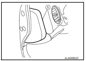
- Using a suitable tool, gently remove the instrument side finisher (LH) (1).
- Remove the instrument lower panel (LH) (1).
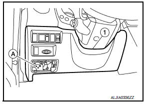
- Open the fuse block cover and remove the instrument lower panel screw (A).
- Disconnect the harness connectors and aspirator hose.
- Remove the instrument lower panel (LH) (1).
INSTALLATION
Installation is in the reverse order of removal.
 Cluster lid D
Removal and Installation
REMOVAL
Release the metal clips using a suitable tool, then position
cluster lid D (1) aside.
Disconnect the harness connectors, then remove cluster lid D
(1).
...
 Glove box assembly
Removal and Installation
REMOVAL
Using a suitable tool, gently remove the instrument panel side
finisher (RH).
Open the glove box door and then remove the glove box assembly
screws (A).
...
Other materials:
Back-up lamp
Wiring Diagram
...
How to park with predicted course lines
WARNING
If the tires are replaced with different
sized tires, the predicted course lines
may be displayed incorrectly.
On a snow-covered or slippery road,
there may be a difference between the
predicted course line and the actual
course line.
If the battery is disconnected or becomes
discha ...
TCM branch line circuit
Diagnosis Procedure
1.CHECK CONNECTOR
Turn the ignition switch OFF.
Disconnect the battery cable from the negative terminal.
Check the following terminals and connectors for damage, bend and
loose connection (unit side and connector
side).
TCM
Harness connector F1
Harness con ...
Nissan Maxima Owners Manual
- Illustrated table of contents
- Safety-Seats, seat belts and supplemental restraint system
- Instruments and controls
- Pre-driving checks and adjustments
- Monitor, climate, audio, phone and voice recognition systems
- Starting and driving
- In case of emergency
- Appearance and care
- Do-it-yourself
- Maintenance and schedules
- Technical and consumer information
Nissan Maxima Service and Repair Manual

0.0054