Nissan Maxima Service and Repair Manual: Normal operating condition
Description
NOTE: For Navigation system operation information, refer to Navigation system Owner's Manual.
BASIC OPERATIONS
NOTE: Locations stored in the Address Book and other memory functions may be lost if the vehicle's battery is disconnected or becomes discharged. If this occurs, service the vehicle's battery as necessary and re-enter the information in the Address Book.
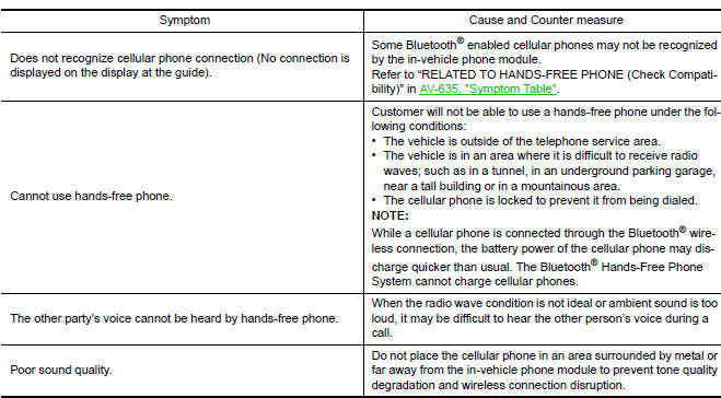
RELATED TO HANDS-FREE PHONE
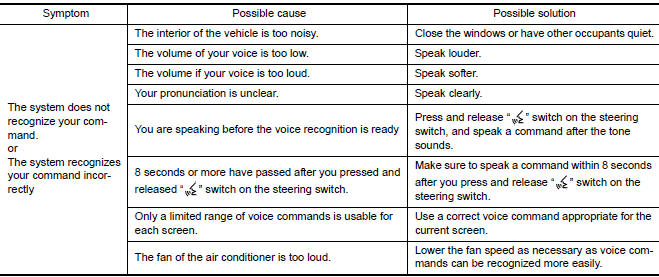
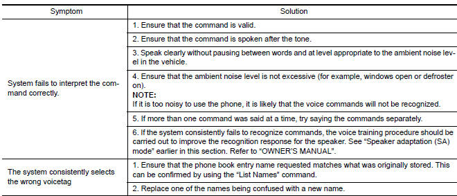
RELATED TO VOICE RECOGNITION
Related to Basic Operation
Related to Item Choice
The system should respond correctly to all voice commands without difficulty. If problems are encountered, follow the solutions given in this guide for the appropriate error.
Where the solutions are listed by number, try each solution in turn, starting with number one, until the problem is resolved.
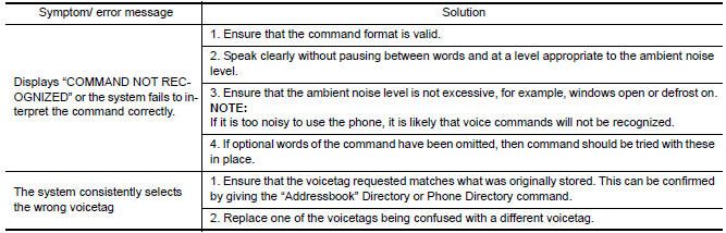
Related to Telephone
The system should respond correctly to all voice commands without difficulty. If problems are encountered, try the following solutions.
Where the solutions are listed by number, try each solution in turn, starting with number 1, until the problem is resolved
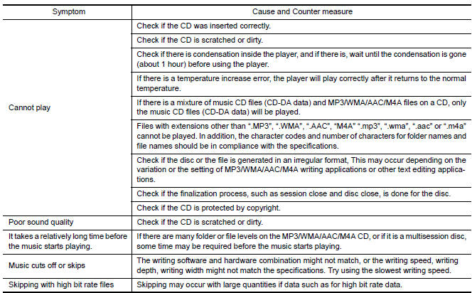
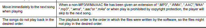
RELATED TO AUDIO
- The majority of the audio malfunctions are the result of outside causes (bad CD/cassette, electromagnetic interference, etc.). Check the symptoms below to diagnose the malfunction.
- The vehicle itself can be a source of noise if noise prevention
parts or electrical equipment is malfunctioning.
Check if noise is caused and/or changed by engine speed, ignition switch turned to each position, and operation of each piece of electrical equipment, and then determine the cause.
NOTE:
- CD-R is not guaranteed to play because they can contain compressed audio (MP3, WMA, AAC, M4A) or could be incorrectly mastered by the customer on a computer.
- Check if the CDs carry the Compact Disc Logo. If not, the disc is not mastered to the "red book" Compact Disc Standard and may not play.
Noise resulting from variations in field strength, such as fading noise and multi-path noise, or external noise from trains and other sources, is not a malfunction.
NOTE:
- Fading noise: This noise occurs because of variations in the field strength in a narrow range due to mountains or buildings blocking the signal.
- Multi-path noise: This noise results from a time difference between the broadcast waves directly from the station arriving at the antenna and the waves reflected by mountains or buildings.
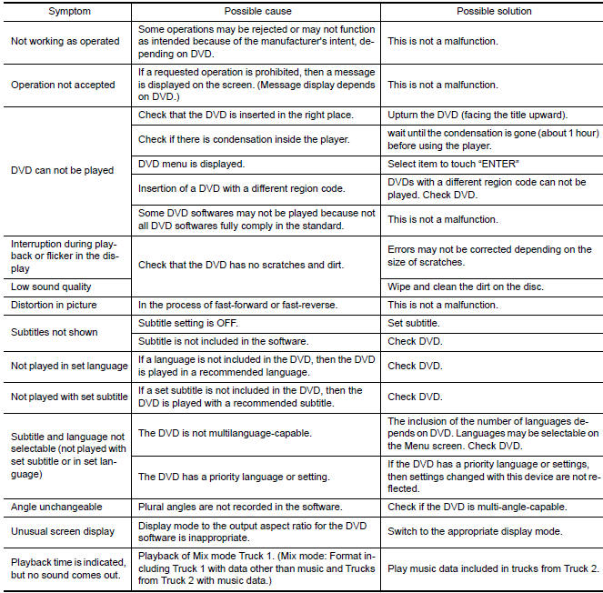
RELATED TO DVD
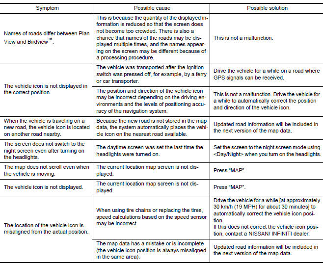
RELATED TO VEHICLE ICON
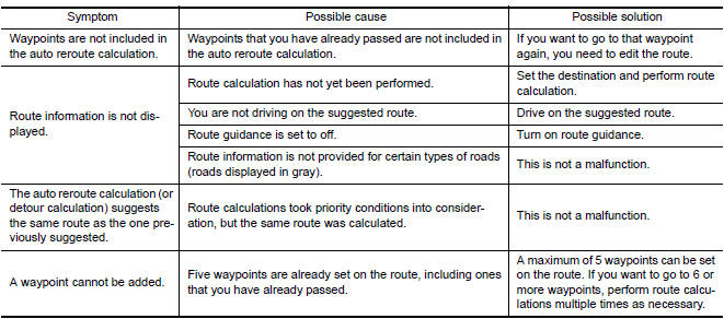
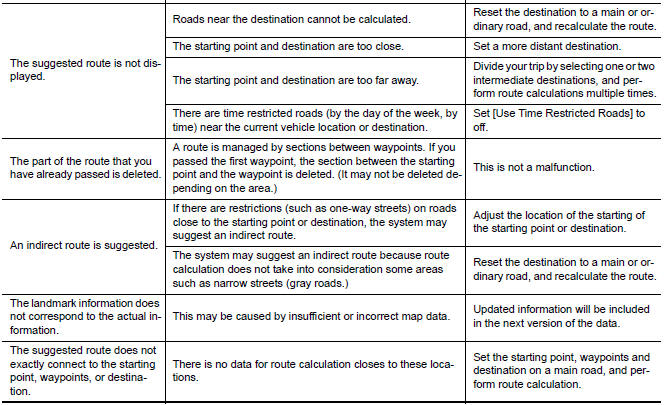
RELATED TO ROUTE CALCULATION AND VISUAL GUIDANCE
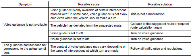
RELATED TO VOICE GUIDANCE
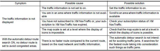
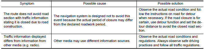
RELATED TO TRAFFIC INFORMATION
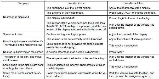
 Multi AV system symptoms
Symptom Table
RELATED TO NAVIGATION
Trouble Diagnosis Chart by Symptom
RELATED TO HANDS-FREE PHONE
Before performing diagnosis, confirm that the cellular phone being
used by the customer ...
 Precaution
Precaution for Supplemental Restraint System (SRS) "AIR BAG" and "SEAT
BELT
PRE-TENSIONER"
The Supplemental Restraint System such as "AIR BAG" and "SEAT BELT
PRE-TENSIONER", ...
Other materials:
Ground
Ground Distribution
MAIN HARNESS
ENGINE ROOM HARNESS
FRONT END MODULE HARNESS
ENGINE CONTROL HARNESS
BODY HARNESS
BODY NO. 2 HARNESS
...
Precautions on cruise control
1. CANCEL switch
2. RES+ switch
3. SET- switch
4. ON/OFF cruise switch
If the cruise control system malfunctions, it
cancels automatically.
WARNING
Do not use the cruise control when driving
under the following conditions:
When it is not possible to keep the
vehicle at ...
The parking brake release warning continues sounding, or does not sound
Description
The parking brake warning buzzer sounds continuously during
vehicle travel though the parking brake is
released
The parking brake warning buzzer does not sound at all even though
driving the vehicle with the parking
brake applied.
Diagnosis Procedure
1. CHECK PARKIN ...
Nissan Maxima Owners Manual
- Illustrated table of contents
- Safety-Seats, seat belts and supplemental restraint system
- Instruments and controls
- Pre-driving checks and adjustments
- Monitor, climate, audio, phone and voice recognition systems
- Starting and driving
- In case of emergency
- Appearance and care
- Do-it-yourself
- Maintenance and schedules
- Technical and consumer information
Nissan Maxima Service and Repair Manual

0.0055