Nissan Maxima Service and Repair Manual: P1078, P1084 EVT control position sensor
Description
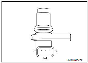
Exhaust valve timing control position sensor detects the concave groove of the exhaust camshaft rear end.
This sensor signal is used for sensing a position of the exhaust camshaft.
This sensor uses a Hall IC.
Based on the position of the exhaust camshaft, ECM controls exhaust valve timing control magnet retarder to optimize the shut/ open timing of exhaust valve for the driving condition.
DTC Logic
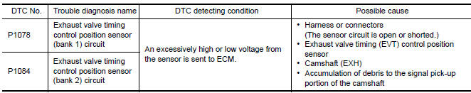
DTC DETECTION LOGIC
NOTE: If DTC P1078 or P1084 is displayed with DTC P0643, first perform the trouble diagnosis for DTC P0643.
Refer to EC-394, "DTC Logic".
DTC CONFIRMATION PROCEDURE
1.PRECONDITIONING
If DTC Confirmation Procedure has been previously conducted, always perform the following procedure before conducting the next test.
- Turn ignition switch OFF and wait at least 10 seconds.
- Turn ignition switch ON.
- Turn ignition switch OFF and wait at least 10 seconds.
2.PERFORM DTC CONFIRMATION PROCEDURE
- Start engine and let it idle for 10 seconds.
- Check 1st trip DTC.
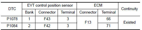
Diagnosis Procedure
1.CHECK GROUND CONNECTION
- Turn ignition switch OFF.
- Check ground connection E9.
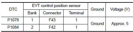
2.CHECK EXHAUST VALVE TIMING (EVT) CONTROL POSITION SENSOR POWER SUPPLY CIRCUIT-I
- Disconnect EVT control position sensor harness connector.
- Turn ignition switch ON.
- Check the voltage between EVT control position sensor harness connector and ground.
3.CHECK EVT CONTROL POSITION SENSOR GROUND CIRCUIT FOR OPEN AND SHORT
- Turn ignition switch OFF.
- Disconnect ECM harness connector.
- Check the continuity between EVT control position sensor harness connector and ECM harness connector.
- Also check harness for short to ground and short to power.
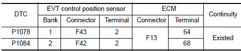
4.CHECK EVT CONTROL POSITION SENSOR INPUT SIGNAL CIRCUIT FOR OPEN AND SHORT
- Check the continuity between EVT control position sensor harness connector and ECM harness connector.
- Also check harness for short to ground and short to power.
5.CHECK EVT CONTROL POSITION SENSOR
6.CHECK CAMSHAFT (EXH)
Check the following.
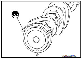
- Accumulation of debris to the signal plate of camshaft rear end
- Chipping signal plate of camshaft rear end
7.CHECK INTERMITTENT INCIDENT
Component Inspection
1.EXHAUST VALVE TIMING CONTROL POSITION SENSOR-I
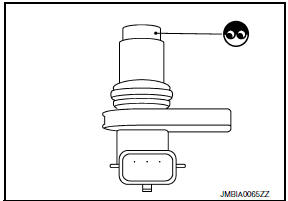
- Turn ignition switch OFF.
- Disconnect exhaust valve timing control position sensor harness connector.
- Loosen the fixing bolt of the sensor.
- Remove the sensor.
- Visually check the sensor for chipping.
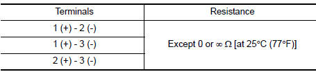
2.EXHAUST VALVE TIMING CONTROL POSITION SENSOR-II
Check resistance exhaust valve timing control position sensor terminals as shown below.
 P0850 PNP switch
Description
When the selector lever position is P or N, park/neutral position (PNP)
signal from the TCM is sent to ECM.
DTC Logic
DTC DETECTION LOGIC
DTC CONFIRMATION PROCEDURE
1.INSPECTION ...
 P1148, P1168 closed loop control
DTC Logic
DTC DETECTION LOGIC
NOTE:
DTC P1148 or P1168 is displayed with another DTC for A/F sensor 1.
Perform the trouble diagnosis for the corresponding DTC.
...
Other materials:
Rear combination lamp
Exploded View
Slide clip
Grommets
Rear combination lamp
Removal and Installation
REAR COMBINATION LAMP
Removal
Remove the trunk side finisher. Refer to INT-36, "Exploded View".
Remove the rear combination lamp nuts.
Pull the rear combination lamp toward the rear of the vehic ...
Power window system
System Diagram
System Description
MAIN POWER WINDOW AND DOOR LOCK/UNLOCK SWITCH
INPUT/OUTPUT SIGNAL CHART
POWER WINDOW AND DOOR LOCK/UNLOCK SWITCH RH
NPUT/OUTPUT SIGNAL CHART
POWER WINDOW OPERATION
Power window system is operable during the retained power
operation timer aft ...
Blower motor control system
System Diagram
System Description
Fan speed is automatically controlled by the temperature setting, ambient
temperature, in-vehicle temperature,
intake temperature, amount of sunload and air mix door position.
By pressing the AUTO switch, the blower motor starts to gradually increase
a ...
Nissan Maxima Owners Manual
- Illustrated table of contents
- Safety-Seats, seat belts and supplemental restraint system
- Instruments and controls
- Pre-driving checks and adjustments
- Monitor, climate, audio, phone and voice recognition systems
- Starting and driving
- In case of emergency
- Appearance and care
- Do-it-yourself
- Maintenance and schedules
- Technical and consumer information
Nissan Maxima Service and Repair Manual

0.0055