
Nissan Maxima Service and Repair Manual: Cluster lid D
Removal and Installation
REMOVAL
- Release the metal clips using a suitable tool, then position cluster lid D (1) aside.
- Disconnect the harness connectors, then remove cluster lid D (1).
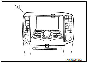
 : Metal clip
INSTALLATION
Installation is in the reverse order of removal.
 Cluster lid C
Removal and Installation
CLUSTER LID C
NOTE: The cluster lid C lower finisher is
only used in vehicles equipped with monochrome display unit.
Removal - With Monochrome Display
Release the cli ...
 Instrument lower panel LH
Removal and Installation
REMOVAL
Using a suitable tool, gently remove the instrument side finisher
(LH) (1).
Remove the instrument lower panel (LH) (1).
Open the fuse block cover a ...
Other materials:
Center console assembly
Exploded View
Center console side finisher (LH)
Center console finisher
CVT finisher
Center console storage bin
Center console screw cover (LH)
Center console rear finisher
Center console screw cover (RH)
Center console
Center console lid assembly
Cup holder
Center cons ...
Diagnosis and repair work flow
Work Flow
INTRODUCTION
The TCM receives signals from the vehicle speed sensor and transmission range
switch. Then it provides shift
control or lock-up control via CVT solenoid valves.
The TCM also communicates with the ECM by means of signals
sent from sensing elements used with the OBD-r ...
Harness
Harness Layout
HOW TO READ HARNESS LAYOUT
The following Harness Layouts use a map style grid to help locate
connectors on the drawings:
Main Harness, Console Sub-harness and Console Switch Subharness
Engine Room Harness and Front End Module Harness
Engine Room Harness (Passenger Comp ...
Nissan Maxima Owners Manual
- Illustrated table of contents
- Safety-Seats, seat belts and supplemental restraint system
- Instruments and controls
- Pre-driving checks and adjustments
- Monitor, climate, audio, phone and voice recognition systems
- Starting and driving
- In case of emergency
- Appearance and care
- Do-it-yourself
- Maintenance and schedules
- Technical and consumer information
Nissan Maxima Service and Repair Manual

0.018