Nissan Maxima Service and Repair Manual: B2190 nats antenna AMP.
Description
Performs ID verification through BCM and Intelligent Key when push-button ignition switch is pressed.
Prohibits the start of engine when an unregistered ID of Intelligent Key is used.
DTC Logic
DTC DETECTION LOGIC
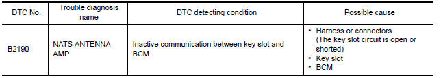
DTC CONFIRMATION PROCEDURE
1.PERFORM DTC CONFIRMATION PROCEDURE
-
Insert Intelligent Key into the key slot.
-
Check "Self Diagnostic Result" with CONSULT.
2.PERFORM DTC CONFIRMATION PROCEDURE
-
Press the push-button ignition switch.
-
Check "Self Diagnostic Result" with CONSULT.
Diagnosis Procedure
Regarding Wiring Diagram information, refer to SEC-147, "Wiring Diagram".
1. INSPECTION START
Check the case in which DTC is detected.
-
Case1: It is detected when Intelligent Key is inserted into key slot.
-
Case2: It is detected after Intelligent Key is inserted into key slot and push-button ignition switch is pressed.
In which case is DTC detected?
Case1. GO TO 2
Case2. GO TO 4
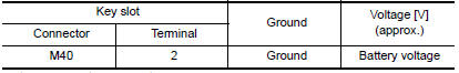
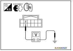
2.CHECK KEY SLOT INPUT SIGNAL
-
Turn ignition switch OFF.
-
Disconnect key slot harness connector.
-
Check voltage between key slot harness connector M40 terminal 2 and ground.
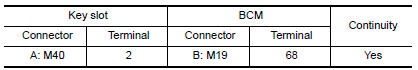
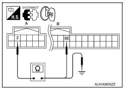
3.CHECK KEY SLOT CIRCUIT
-
Disconnect BCM harness connector.
-
Check continuity between key slot harness connector M40 (A) terminal 2 and BCM harness connector M19 (B) terminal 68.
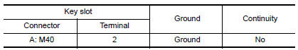
3. Check continuity between key slot harness connector M40 (A) terminal 2 and ground.
4.CHECK PUSH-IGNITION SWITCH OPERATION
Press push-button ignition switch and check if it turns ON.
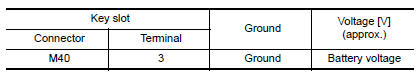
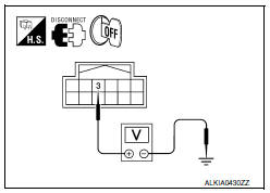
5.CHECK KEY SLOT COMMUNICATION SIGNAL
-
Turn ignition switch OFF.
-
Disconnect key slot harness connector.
-
Check voltage between key slot harness connector M40 terminal 3 and ground.
6.CHECK KEY SLOT COMMUNICATION SIGNAL CIRCUIT
-
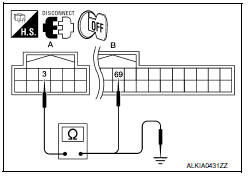
Disconnect BCM harness connector.
-
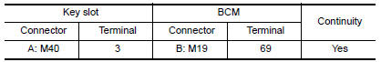
Check continuity between key slot harness connector M40 (A) terminal 3 and BCM harness connector M19 (B) terminal 69.
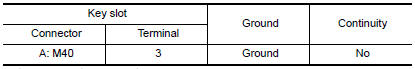
3. Check continuity between key slot harness connector M40 (A) terminal 3 and ground.
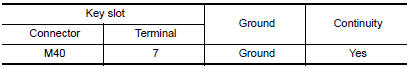
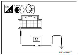
7.CHECK KEY SLOT GROUND CIRCUIT
-
Turn ignition switch OFF.
-
Disconnect key slot harness connector.
-
Check continuity between key slot harness connector M40 terminal 7 and ground.
8.CHECK INTERMITTENT INCIDENT
Refer to GI-41, "Intermittent Incident".
Inspection End.
 P1615 diffrence of key
Description
Performs ID verification through BCM and Intelligent Key
when push-button ignition switch is pressed.
Prohibits the start of engine when an unregistered ID of Intelligent Key is
us ...
 B2191 difference of key
Description
Performs ID verification through BCM and Intelligent Key
when push-button ignition switch is pressed.
Prohibits the start of engine when an unregistered ID of Intelligent Key is
us ...
Other materials:
On board diagnostic (OBD) system
Diagnosis Description
This system is an on board diagnostic system that records exhaust
emission-related diagnostic information
and detects a sensors/actuator-related malfunction. A malfunction is indicated
by the malfunction indicator
lamp (MIL) and stored in ECU memory as a DTC. The diagn ...
General maintenance
During the normal day-to-day operation of the
vehicle, general maintenance should be performed
regularly as prescribed in this section. If
you detect any unusual sounds, vibrations or
smells, be sure to check for the cause or have a
NISSAN dealer do it promptly. In addition, it is
recommended ...
Bluetooth control unit
Reference Value
TERMINAL LAYOUT
PHYSICAL VALUES
...
Nissan Maxima Owners Manual
- Illustrated table of contents
- Safety-Seats, seat belts and supplemental restraint system
- Instruments and controls
- Pre-driving checks and adjustments
- Monitor, climate, audio, phone and voice recognition systems
- Starting and driving
- In case of emergency
- Appearance and care
- Do-it-yourself
- Maintenance and schedules
- Technical and consumer information
Nissan Maxima Service and Repair Manual

0.0062