Nissan Maxima Owners Manual: Speedometer and odometer
This vehicle is equipped with a speedometer and odometer. The speedometer is located on the right side of the meter cluster. The odometer is located within the vehicle information display.
Speedometer
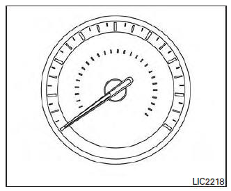
The speedometer indicates vehicle speed.
Odometer/Twin trip odometer
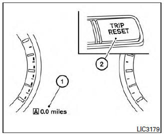
The odometer and the twin trip odometer 1 are displayed in the vehicle information display when the ignition switch is placed in the ON position.
The odometer records the total distance the vehicle has been driven.
The twin trip odometer records the distance of individual trips.
Changing the display
Push the TRIP RESET 2 switch on the left side of the instrument panel to change the display as follows: Trip A →Trip B→Odometer Mileage→ Trip A
Resetting the trip odometer
Pushing the TRIP RESET switch 2 for more than 1 second resets the currently displayed trip odometer to zero.
Average fuel economy and distance to empty information is also available. For additional information, refer to "Vehicle information display" in this section.
 Meters and gauges
Tachometer
Warning and indicator lights
Vehicle information display. Odometer. Twin trip odometer
Speedometer
Fuel gauge
Engine coolant temperature gauge
...
 Tachometer
The tachometer indicates engine speed in revolutions
per minute (rpm). Do not rev engine into
the red zone 1 .
CAUTION
When engine speed approaches the red
zone, reduce engine speed. Operating ...
Other materials:
ADP branch line circuit
Diagnosis Procedure
1.CHECK CONNECTOR
Turn the ignition switch OFF.
Disconnect the battery cable from the negative
terminal.
Check the following terminals and connectors
for damage, bend and loose connection (unit side and connector
side).
...
Automatic anti-glare rearview mirror
The inside mirror is designed so that it automatically
dims during night time conditions and according
to the intensity of the headlights of the
vehicle following you. The automatic anti-glare
feature is activated when the ignition switch is in
the ON position.
The indicator light will i ...
Preparation
Special Service Tool
The actual shapes of the tools may differ from those illustrated her
Commercial Service Tool
...
Nissan Maxima Owners Manual
- Illustrated table of contents
- Safety-Seats, seat belts and supplemental restraint system
- Instruments and controls
- Pre-driving checks and adjustments
- Monitor, climate, audio, phone and voice recognition systems
- Starting and driving
- In case of emergency
- Appearance and care
- Do-it-yourself
- Maintenance and schedules
- Technical and consumer information
Nissan Maxima Service and Repair Manual

0.0052