Nissan Maxima Owners Manual: Meters and gauges
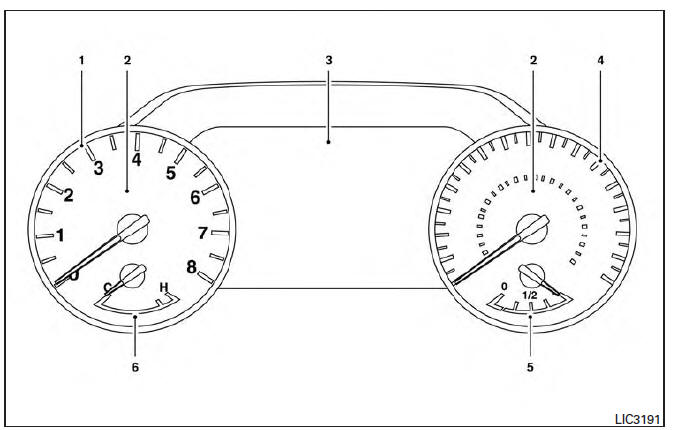
- Tachometer
- Warning and indicator lights
- Vehicle information display. Odometer. Twin trip odometer
- Speedometer
- Fuel gauge
- Engine coolant temperature gauge
 Instrument Panel
Vent
Headlight/fog light/turn signal switch
Supplemental front-impact air bag. Horn
Meters and gauges. Warning and indicator lights. Vehicle information
display
Paddle shifters (if s ...
 Speedometer and odometer
This vehicle is equipped with a speedometer and
odometer. The speedometer is located on the
right side of the meter cluster. The odometer is
located within the vehicle information display.
Speedom ...
Other materials:
AV control unit
Reference Value
VALUES ON THE DIAGNOSIS TOOL
CONSULT data monitor item
TERMINAL LAYOUT
PHYSICAL VALUES
*1 With satellite radio
DTC Index
Self-diagnosis results display item
...
Inspection and adjustment
ADDITIONAL SERVICE WHEN REPLACING CONTROL UNIT
ADDITIONAL SERVICE WHEN REPLACING CONTROL UNIT : Description
MEMORY RESET PROCEDURE
Please observe the following instructions at confirming the sunroof
operation. NOTE: Do not
disconnect the electronic power while the sunroof is operating or ...
Installing the spare tire
The spare tire is designed for emergency
use. For additional information, refer to
"Wheels and tires" in the "Do-it-yourself"
section of this manual.
1. Clean any mud or dirt from the surface between
the wheel and hub.
2. Carefully put the spare tire on and tighten
the wheel nuts finger ...
Nissan Maxima Owners Manual
- Illustrated table of contents
- Safety-Seats, seat belts and supplemental restraint system
- Instruments and controls
- Pre-driving checks and adjustments
- Monitor, climate, audio, phone and voice recognition systems
- Starting and driving
- In case of emergency
- Appearance and care
- Do-it-yourself
- Maintenance and schedules
- Technical and consumer information
Nissan Maxima Service and Repair Manual

0.0052