
Nissan Maxima Service and Repair Manual: Stall test
Inspection and Judgment
INSPECTION
-
Inspect the amount of engine oil. Replenish the engine oil if necessary.
-
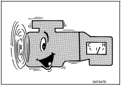
Drive for about 10 minutes to warm up the vehicle so that the CVT fluid temperature is 50 to 80C (122 to 176F). Inspect the amount of CVT fluid. Replenish if necessary.
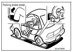
3. Securely engage parking brake so that the tires do not turn.
4. Install a tachometer where it can be seen by driver during test.
NOTE: It is good practice to mark the point of specified engine rpm on indicator.
5. Start engine, apply foot brake, and move selector lever to "D" position.
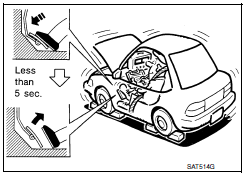
6. Gradually press down accelerator pedal while holding down the foot brake.
7. Quickly read off the stall speed, and then quickly remove your foot from accelerator pedal.
CAUTION: Never hold down accelerator pedal for more than 5 seconds during this test.
8. Move selector lever to "N" position.
9. Cool down the CVT fluid.
CAUTION: Run the engine at idle for at least 1 minute.
10. Repeat steps 6 through 9 with selector lever in "R" position.
JUDGMENT
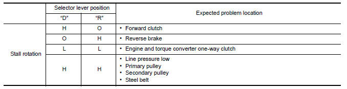
O: Stall speed within standard value position.
H: Stall speed is higher than standard value.
L: Stall speed is lower than standard value.
 CVT fluid cooler system
Cleaning
Whenever an automatic transaxle is repaired, overhauled,
or replaced, the CVT fluid cooler mounted in the
radiator must be inspected and cleaned.
Metal debris and friction material, i ...
 Line pressure test
Inspection and Judgment
INSPECTION
Line Pressure Test Procedure
Inspect the amount of engine oil and replenish
if necessary.
Drive the car for about 10 minutes to warm ...
Other materials:
Precautions on seat belt usage
If you are wearing your seat belt properly adjusted
and you are sitting upright and well back in
your seat with both feet on the floor, your chances
of being injured or killed in a collision and/or the
severity of injury may be greatly reduced.
NISSAN strongly encourages you and all of yo ...
Cooling system
Cooling Circuit
Cylinder block (RH)
Oil cooler
Cylinder head (RH)
Water pump
Radiator
Water inlet
Thermostat
Cylinder head (LH)
Cylinder block (LH)
To heater
To electric throttle control actuator
From heater
From electric throttle control act ...
Power seat for passenger side
Wiring Diagram
...
Nissan Maxima Owners Manual
- Illustrated table of contents
- Safety-Seats, seat belts and supplemental restraint system
- Instruments and controls
- Pre-driving checks and adjustments
- Monitor, climate, audio, phone and voice recognition systems
- Starting and driving
- In case of emergency
- Appearance and care
- Do-it-yourself
- Maintenance and schedules
- Technical and consumer information
Nissan Maxima Service and Repair Manual

0.0103