Nissan Maxima Service and Repair Manual: CVT fluid cooler system
Cleaning
Whenever an automatic transaxle is repaired, overhauled, or replaced, the CVT fluid cooler mounted in the radiator must be inspected and cleaned.
Metal debris and friction material, if present, can be trapped or be deposited in the CVT fluid cooler. This debris can contaminate the newly serviced CVT or, in severe cases, can block or restrict the flow of CVT fluid.
In either case, malfunction of the newly serviced CVT may occur.
Debris, if present, may deposit as CVT fluid enters the cooler inlet. It will be necessary to back flush the cooler through the cooler outlet in order to flush out any built up debris.
CVT FLUID COOLER CLEANING PROCEDURE
-
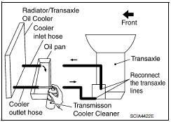
Position an oil pan under the transaxle's inlet and outlet cooler hoses.
-
Identify the inlet and outlet fluid cooler hoses.
-
Disconnect the fluid cooler inlet and outlet rubber hoses from the steel cooler tubes or bypass valve.
NOTE: Replace the cooler hoses if rubber material from the hose remains on the tube fitting.
-
Allow any CVT fluid that remains in the cooler hoses to drain into the oil pan.
5 Insert the extension adapter hose of a can of Transmission Cooler Cleaner (Nissan P/N 999MP-AM006) into the cooler outlet hose.
CAUTION:
-
Wear safety glasses and rubber gloves when spraying the Transmission Cooler Cleaner.
-
Spray Transmission Cooler Cleaner only with adequate ventilation.
-
Avoid contact with eyes and skin.
-
Do not breath vapors or spray mist.
6. Hold the hose and can as high as possible and spray Transmission Cooler Cleaner in a continuous stream into the cooler outlet hose until CVT fluid flows out of the cooler inlet hose for 5 seconds.
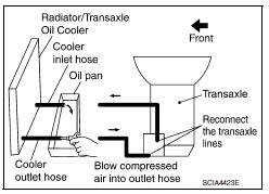
7. Insert the tip of an air gun into the end of the cooler outlet hose.
8. Wrap a shop rag around the air gun tip and end of the cooler outlet hose.
9. Blow compressed air regulated to 5 to 9 kg/cm2 (70 to 130 psi) through the cooler outlet hose for 10 seconds to force out any remaining CVT fluid.
10. Repeat steps 5 through 9 three additional times.
11. Position an oil pan under the banjo bolts that connect the CVT fluid cooler steel lines to the transaxle.
12. Remove the banjo bolts.
13. Flush each steel line from the cooler side back toward the transaxle by spraying Transmission Cooler Cleaner in a continuous stream for 5 seconds.
14. Blow compressed air regulated to 5 to 9 kg/cm2 (70 to 130 psi) through each steel line from the cooler side back toward the transaxle for 10 seconds to force out any remaining CVT fluid.
15. Ensure all debris is removed from the steel cooler lines.
16. Ensure all debris is removed from the banjo bolts and fittings.
17. Perform "CVT FLUID COOLER DIAGNOSIS PROCEDURE".
CVT FLUID COOLER DIAGNOSIS PROCEDURE
NOTE: Insufficient cleaning of the cooler inlet hose exterior may lead to inaccurate debris identification.
-
Position an oil pan under the transaxle's inlet and outlet cooler hoses.
-
Clean the exterior and tip of the cooler inlet hose.
-
Insert the extension adapter hose of a can of Transmission Cooler Cleaner (Nissan P/N 999MP-AM006) into the cooler outlet hose.
CAUTION:
-
Wear safety glasses and rubber gloves when spraying the Transmission Cooler Cleaner.
-
Spray Transmission Cooler Cleaner only with adequate ventilation.
-
Avoid contact with eyes and skin.
-
Do not breath vapors or spray mist.
4. Hold the hose and can as high as possible and spray Transmission Cooler Cleaner in a continuous stream into the cooler outlet hose until CVT fluid flows out of the cooler inlet hose for 5 seconds.
5. Tie a common white, basket-type coffee filter to the end of the cooler inlet hose.
6. Insert the tip of an air gun into the end of the cooler outlet hose.
7. Wrap a shop rag around the air gun tip and end of cooler outlet hose.
8. Blow compressed air regulated to 5 to 9 kg/cm2 (70 to 130 psi) through the cooler outlet hose to force any remaining CVT fluid into the coffee filter.
9. Remove the coffee filter from the end of the cooler inlet hose.
10. Perform "CVT FLUID COOLER INSPECTION PROCEDURE".
CVT FLUID COOLER INSPECTION PROCEDURE
-
Inspect the coffee filter for debris.
-
a. If small metal debris less than 1 mm (0.040 in) in size or metal powder is found in the coffee filter, this is normal. If normal debris is found, the CVT fluid cooler/radiator can be reused and the procedure is ended.
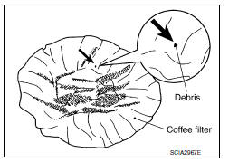
b. If one or more pieces of debris are found that are over 1 mm (0.040 in) in size and/or peeled clutch facing material is found in the coffee filter, the fluid cooler is not serviceable. The radiator/ fluid cooler must be replaced and the inspection procedure is ended. Refer to CO-14, "Removal and Installation".
CVT FLUID COOLER FINAL INSPECTION
After performing all procedures, ensure that all remaining oil is cleaned from all components.
 CVT fluid
Inspection
CHECKING CVT FLUID
The fluid level should be checked with the fluid warmed
up to 50 to 80C (122 to 176F). The fluid level
check procedure is as follows:
Check for fluid l ...
 Stall test
Inspection and Judgment
INSPECTION
Inspect the amount of engine oil. Replenish the
engine oil if necessary.
Drive for about 10 minutes to warm up the
vehicle so that ...
Other materials:
Bose speaker AMP\
Removal and Installation
Bose speaker amp.
Screws
REMOVAL
NOTE:
If removing the BOSE speaker amp. bracket, it is necessary to remove the parcel
shelf finisher. The BOSE
speaker amp. can be removed without removing the BOSE speaker amp. bracket.
Disconnect the battery negativ ...
B1129 - B1132 side airbag module RH
Description
DTC B1129 - B1132 FRONT RH SIDE AIR BAG MODULE
The front RH side air bag module is wired to the air bag diagnosis sensor
unit. The air bag diagnosis sensorunit will monitor for opens and shorts in
detected lines to the front RH side air bag module.
PART LOCATION
DTC Logic
DTC DE ...
U0415 Vehicle speed sig
Description
U0415 is displayed if any unusual condition is present in the reception
status of the vehicle speed signal from
the ABS actuator and electric unit (control unit).
DTC Logic
DTC DETECTION LOGIC
DTC CONFIRMATION PROCEDURE
1. DTC CONFIRMATION
Erase the DTC.
Turn ignition ...
Nissan Maxima Owners Manual
- Illustrated table of contents
- Safety-Seats, seat belts and supplemental restraint system
- Instruments and controls
- Pre-driving checks and adjustments
- Monitor, climate, audio, phone and voice recognition systems
- Starting and driving
- In case of emergency
- Appearance and care
- Do-it-yourself
- Maintenance and schedules
- Technical and consumer information
Nissan Maxima Service and Repair Manual

0.0196