
Nissan Maxima Owners Manual: Instrument Panel
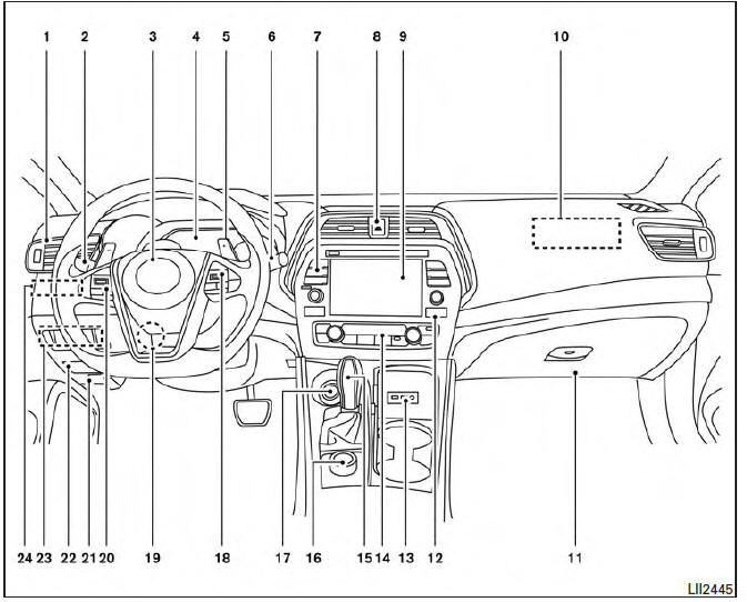
- Vent
- Headlight/fog light/turn signal switch
- Supplemental front-impact air bag. Horn
- Meters and gauges. Warning and indicator lights. Vehicle information display
- Paddle shifters (if so equipped)
- Wiper and washer switch
- Audio controls*. Navigation controls*
- Hazard warning flasher switch
- Navigation display*. Audio display*
- Front passenger supplemental air bag
- Glove box
- Front passenger air bag status light
- AUX input/USB port*
- Heater and air conditioning controls
- Shift lever
- Display Commander*
- Push-button ignition switch
- Bluetooth Hands-Free Phone System. Intelligent Cruise Control (ICC) switches (if so equipped).
- Tilt and telescopic steering
- Audio control switches*. Vehicle information display control switches
- Hood release
- Fuse box
- Heated steering wheel switch (if so equipped). Vehicle Dynamic Control (VDC) OFF switch. Trunk release switch. Rear power sunshade switch (if so equipped)
- Instrument brightness control. Twin trip odometer reset switch
*: Refer to the separate Navigation System Owner's Manual.
Refer to the page number indicated in parentheses for operating details.

 Meters and gauges
Tachometer
Warning and indicator lights
Vehicle information display. Odometer. Twin trip odometer
Speedometer
Fuel gauge
Engine coolant temperature gauge
...
Other materials:
Insufficient cooling
Component Function Check
Symptom
Insufficient cooling
No cool air comes out. (Airflow volume is normal.)
INSPECTION FLOW
1. CONFIRM SYMPTOM BY PERFORMING OPERATION CHECK - TEMPERATURE DECREASE
Press the AUTO switch.
Turn temperature control dial (driver side) counterclockwise until ...
Compressor control function
Description
PRINCIPLE OF OPERATION
A/C compressor is not activated.
Functional circuit diagram
CAN (1): A/C switch signal
: Blower fan motor switch signal
CAN (2): A/C compressor request signal
RX: A/C switch signal
: Fan ON signal
: Defroster signal
Functional initial inspection chart ...
IPDM E/R (intelligent power distribution module engine room)
IPDM E/R (INTELLIGENT POWER DISTRIBUTION MODULE ENGINE
ROOM) : Diagnosis
Procedure
Regarding Wiring Diagram information, refer to PCS-28,
"Wiring Diagram".
1. CHECK FUSES AND FUSIBLE LINK
Check that the following IPDM E/R fuses or fusible link
are not blown.
2. CHECK POWER SUPPLY CIRCU ...
Nissan Maxima Owners Manual
- Illustrated table of contents
- Safety-Seats, seat belts and supplemental restraint system
- Instruments and controls
- Pre-driving checks and adjustments
- Monitor, climate, audio, phone and voice recognition systems
- Starting and driving
- In case of emergency
- Appearance and care
- Do-it-yourself
- Maintenance and schedules
- Technical and consumer information
Nissan Maxima Service and Repair Manual

0.0098