Nissan Maxima Service and Repair Manual: NVIS (NISSAN vehicle immobilizer system-nats)
System Diagram
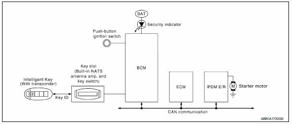
System Description
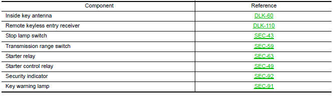
INPUT/OUTPUT SIGNAL CHART
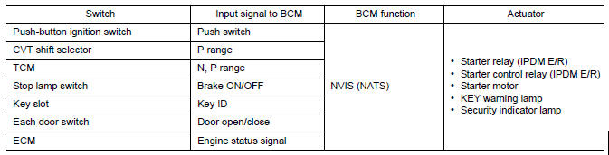
SYSTEM DESCRIPTION
- The NVIS (NATS) is an anti-theft system. By registering an Intelligent Key ID into the vehicle, it prevents the engine being started by an unregistered Intelligent Key. It has a higher protection against auto thefts than duplicate mechanical keys.
- It performs the ID verification when starting the engine in the same way as the Intelligent Key system. But, it performs the NVIS (NATS) ID verification when inserting the Intelligent Key and performs the Intelligent Key ID verification when carrying the Intelligent Key.
- The Intelligent Key system of A35 is not the same as the conventional models. The mechanical key integrated in the Intelligent Key cannot start the engine. When the Intelligent Key battery is discharged, the NVIS (NATS) ID verification memorized to the transponder integrated with Intelligent Key is performed by inserting the Intelligent Key into the key slot. If the verification results are OK, the engine start operation can be performed by the push-button ignition switch operation.
- Locate the security indicator and apply the anti-theft system equipment sticker, forewarning that the NVIS (NATS) is onboard with the model.
- The security indicator always blinks when the Intelligent Key is removed from the key slot and when the power supply position is in LOCK position.
- Intelligent Key can be registered up to 4 keys (Including the standard ignition key) on request from the owner.
- The specified registration is required when replacing ECM, BCM or Intelligent Key. For registration procedure for NVIS (NATS) and registration procedure for Intelligent Key when installing the BCM, refer to CONSULT Immobilizer mode and follow the on-screen instructions.
- Possible symptom of NVIS (NATS) malfunction is "Engine cannot
start". In A35, the engine can be started
with the Intelligent Key system and NVIS (NATS). Identify the possible
causes according to "Work Flow".
Refer to SEC-4, "Work Flow"
- If ECM other than Genuine NISSAN is installed, the engine cannot be started. For ECM replacement procedure, refer to SEC-9, "ECM RE-COMMUNICATING FUNCTION : Special Repair Requirement".
PRECAUTIONS FOR KEY REGISTRATION
- The key registration is a procedure that erases the current NVIS (NATS) ID once, and then re-registers a new ID operation. Therefore, the registered Intelligent Key is necessary for this procedure. Before starting the registration operation collect all registered Intelligent Keys from the customer
- When registering the Intelligent Key, perform only one procedure
to register simultaneously both ID (NVIS
"NATS" ID registration and Intelligent Key ID registration).
The NVIS (NATS) ID registration is the procedure that registers the ID stored into the transponder (integrated in Intelligent Key) to BCM.
The Intelligent Key ID registration is the procedure that registers the ID to BCM.
- When performing the Intelligent Key system registration only, the engine cannot be started by inserting the key into the key slot. When performing the NVIS (NATS) registration only, the engine cannot be started by the operation when carrying the key. The registrations of both systems should be performed.
SECURITY INDICATOR
- Warns that the vehicle is equipped with NVIS (NATS).
- The security indicator always blinks when the Intelligent Key is removed from the key slot and when the ignition switch is in LOCK position.
NOTE:
Because security indicator is highly efficient, the battery is barely affected.
Component Parts Location
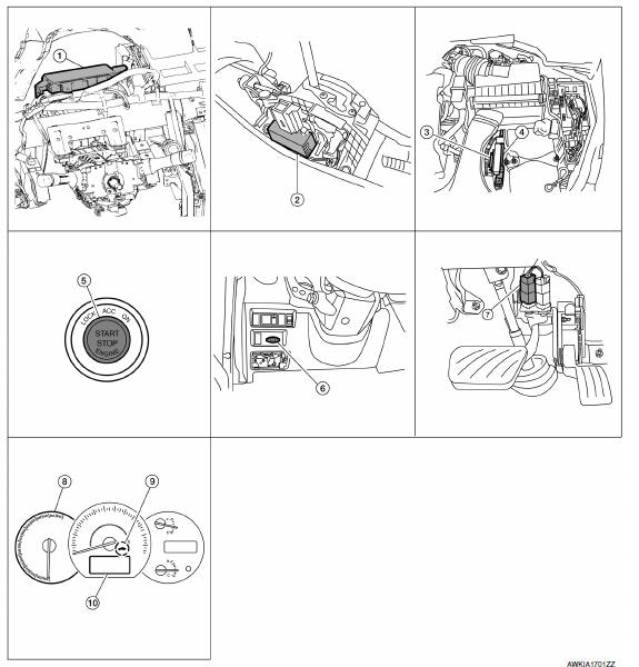
- BCM M16, M17, M18, M19, M21 (view with instrument panel removed)
- CVT shift selector M78
- TCM F15
- ECM E10
- Push button ignition switch M38
- Key slot M40
- Stop lamp switch E38 (view with lower LH instrument panel removed)
- Combination meter M24
- Security indicator lamp
- Information display
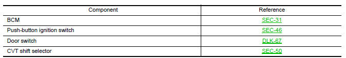
Component Description
 System description
INTELLIGENT KEY SYSTEM/ENGINE START FUNCTION
System Diagram
System Description
INPUT/OUTPUT SIGNAL CHART
SYSTEM DESCRIPTION
The engine start function of Intelligent Key system is a system ...
 Vehicle security system
System Diagram
System Description
INPUT/OUTPUT SIGNAL CHART
OPERATION FLOW
SETTING THE VEHICLE SECURITY SYSTEM
Initial Condition
Ignition switch is in OFF position.
Disar ...
Other materials:
Precaution
PRECAUTIONS
Precaution for Supplemental Restraint System (SRS) "AIR BAG" and
"SEAT BELT PRE-TENSIONER"
The Supplemental Restraint System such as "AIR BAG" and "SEAT BELT
PRE-TENSIONER", used along with a front seat belt, helps to reduce the risk
or severity of injury to the driver and front ...
Tire labeling
Example
Federal law requires tire manufacturers to
place standardized information on the
sidewall of all tires. This information identifies
and describes the fundamental
characteristics of the tire and also provides
the tire identification number (TIN)
for safety standard certification. The ...
Center speaker
Removal and Installation
REMOVAL
Remove the center speaker grille, using a suitable tool.
Remove the center speaker screws (A).
Pull out the center speaker (1), disconnect the harness connector
from the center speaker and remove.
INSTALLATION
Installation is in the reverse order ...
Nissan Maxima Owners Manual
- Illustrated table of contents
- Safety-Seats, seat belts and supplemental restraint system
- Instruments and controls
- Pre-driving checks and adjustments
- Monitor, climate, audio, phone and voice recognition systems
- Starting and driving
- In case of emergency
- Appearance and care
- Do-it-yourself
- Maintenance and schedules
- Technical and consumer information
Nissan Maxima Service and Repair Manual

0.0054